Magnetism and electricity: Identify, describe and apply properties of electricity in an electric circuit
Unit 3: Voltage in an electric circuit
Leigh Kleynhans
Unit outcomes
By the end of this unit you will be able to:
- Define electrical potential difference (voltage) and emf.
- Give examples of sources of potential difference and emf.
- Determine potential change when cells are grouped.
- Determine potential division in a series circuit.
What you should know
Before you start this unit, make sure you can:
- Apply the basic principles of electrical circuits.
- Apply the concepts of electrical current, as covered in Subject outcome 4.3, Unit 1.
- Apply the concepts of resistance in an electric circuit, as covered in Subject outcome 4.3, Unit 2.
Introduction
When a circuit is connected and complete, charge can move through the circuit. Charge will not move unless there is a reason, a force to drive it around the circuit. Think of it as though charge is at rest and something has to push it along. This means that work needs to be done to make charge move. A force acts on the charges, doing work, to make them move. The force is provided by the battery in the circuit.
Potential difference (voltage)
A battery has the potential to drive charge around a closed circuit, the battery has potential energy that can be converted into electrical energy by doing work on the charges in the circuit to make them move. The charges then carry this electrical energy around the circuit.
is defined as the work done per unit of charge.
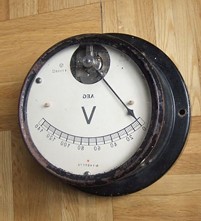
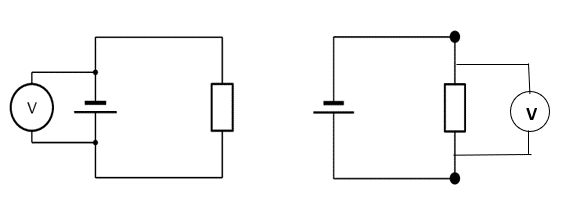
A is an instrument for measuring the potential difference between two points in an electric circuit. The units of potential difference are (V). Potential difference can also be referred to as .

One lead of the voltmeter is connected to one end of the battery and the other lead is connected to the opposite end of the battery. The voltmeter may also be used to measure the voltage across a resistor or any other component of a circuit but must be connected in parallel (Figure 2).
Electromotive force (emf)
When you buy a battery there is a voltage label on the casing.
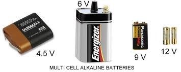
These values indicate the (emf) of the battery. They are given in volts (V) but the values are not exactly the same as the voltage reading when a battery is connected in a circuit.
Activity 3.1: Determine the difference between potential difference (voltage) and emf
Time required: 5 minutes
What you need:
- internet access
What to do:
- Open the link for the PHeT virtual circuit construction lab.

- Click on Lab.
- Build a circuit with a battery of two cells, one resistor, a switch and a voltmeter connected in parallel across the battery.
- Note the reading on the voltmeter when the switch is open.
- Click on Advanced and use the slider in the ‘battery resistance’ block to set the battery resistance at 2 Ω.
- Close the switch and take note of what happens to the voltmeter reading.
What did you find?
The voltmeter reading is higher when the switch is open (no charges flowing in the circuit). When the switch is closed (charges are flowing), the voltmeter reading drops.
When you measure the potential difference across (or between) the terminals of a battery that is in an open circuit, you are measuring the emf of the battery. This is the maximum possible amount of work per coulomb of charge that the battery can do to drive charge from one terminal, through the circuit, to the other terminal.
When the circuit is closed and charges start to flow, some work is required to drive the charges through the battery itself. All batteries will have a certain amount of resistance to the flow of charge. The voltmeter then reads the voltage between the terminals of the battery after the charges have already done some work. This reading will always be lower than the emf. The difference between the readings is the work done per coulomb of charge to drive the charges through the battery itself.
Sources of potential difference and emf
If potential difference is the work done per coulomb of charge, sources of potential difference create a situation where charges at one point have more energy than at another point. In cells, this happens as a result of a chemical reaction. (You will cover this in further chemistry sections.) A potential difference will be created until the chemicals are depleted. The charges will flow in one direction (DC).
A potential difference can also be created in power stations using the interaction of movement and magnetic fields. (You will learn more about this in your physics modules). The source of the movement can be hot water which causes steam, or falling water, solar panels or wind turbines.

Figure 4: A variety of voltage sources (clockwise from top left): the Brazos Wind Farm in Fluvanna, Texas (credit: Leaflet, Wikimedia Commons); the Krasnoyarsk Dam in Russia (credit: Alex Polezhaev); a solar farm (credit: U.S. Department of Energy); and a group of nickel metal hydride batteries (credit: Tiaa Monto).
Voltage and grouping cells to make batteries
A number of cells connected together forms a battery. There are two ways of connecting cells together to form a battery:
Cells in series
To create , the positive terminal of one cell is connected to the negative terminal of the next cell. Charges move through all the cells, therefore the potential difference across the battery will be the sum of the potential difference in each cell.
[latex]\scriptsize {{\text{V}}_{{\text{battery}}}}\text{ = }{{\text{V}}_{{\text{cell 1}}}}\text{ + }{{\text{V}}_{{\text{cell 2}}}}\text{ + }{{\text{V}}_{{\text{cell 3}}}}\text{ }...[/latex]
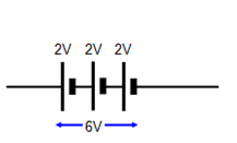
Because the voltage increases with every cell added in series, the charges will have more electrical energy. An example of where this type of connection is used would be in a torch as the higher voltage would result in increased brightness.
Cells in parallel
For , all the positive terminals of the cells are connected together, and all the negative terminals are connected together. Charges have alternative pathways, and each charge only passes through one cell and thus only has the amount of energy provided by one cell. The voltage of the battery will be equivalent to the voltage of one cell.
Adding cells in parallel will not increase the voltage of the battery, however, the battery will last longer. This arrangement is used in devices that do not require high voltages but are used for long periods, for example a clock.
Exercise 3.1
- Six [latex]\scriptsize \text{1,5 V}[/latex] cells are connected in series. What is the voltage of the battery?
- Four [latex]\scriptsize \text{1,5 V}[/latex] cells are connected in parallel. What is the voltage of the battery?
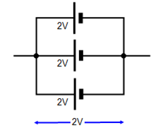
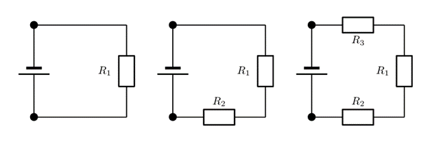
- The cells in the circuit diagrams below are each [latex]\scriptsize \text{2 V}[/latex]. Determine the voltage of the battery:
- .
- .
- .
The full solutions are at the end of the unit.
Potential difference across resistors in a series circuit
When we add to a circuit, there is only one path for current to flow. All the charges have to go through all the resistors.
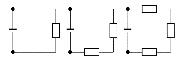
When resistors are added in series the current is the same at every point in the circuit. If you remember what you learnt in Unit 2, the total resistance (load) in a circuit determines how fast the charges can flow (the current). As resistors are added in series the total resistance increases, so the current decreases.
The voltage of the battery, however, is shared across the resistors. This is because the charges will do work (transfer energy) as they move through each resistor. The voltage across the battery in the circuit is equal to the sum of voltages across the all the series resistors:
[latex]\scriptsize {{\text{V}}_{{\text{battery}}}}\text{ = }{{\text{V}}_{{\text{resistor1}}}}+\text{ }{{\text{V}}_{{\text{resistor 2}}}}+\text{ }{{\text{V}}_{{\text{resistor 3}}}}...[/latex]
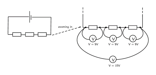
Let us look at this in a bit more detail. In the picture below you can see what the different measurements for three identical resistors in series could look like. The total voltage across all three resistors is the sum of the voltages across the individual resistors. Resistors in series are known as voltage dividers because the total voltage is divided amongst the individual resistors.
Activity 3.2: Determine the potential division in a series circuit
Time required: 10 minutes
What you need:
- internet access
What to do:
- Open the link for the PHeT virtual circuit construction lab.

- Click on Lab.
- Construct the circuits illustrated below, and for each circuit use the voltmeter to measure the voltage of the battery and each resistor.
What did you find?
- When one resistor is connected (R1), the voltage across the resistor is equal to the voltage across the battery.
- When two resistors are connected in series ([latex]\scriptsize {{\text{R}}_{\text{1}}}\text{ and }{{\text{R}}_{\text{2}}}[/latex]), the voltage across the battery is shared between them. Each resistor gets half the voltage.
- When three resistors are connected in series ([latex]\scriptsize {{\text{R}}_{\text{1}}}\text{, }{{\text{R}}_{\text{2}}}\text{ and }{{\text{R}}_{3}}[/latex]), the voltage across the battery is shared between all three resistors. Each resistor gets one third of the voltage.
In Activity 3.2 the resistors are identical, so the voltage of the battery is divided equally. If there are resistors of different resistance in series, the voltage is divided in proportion to their resistance. The greater the resistance, the more energy is transferred per coulomb, therefore the voltage will be greater.
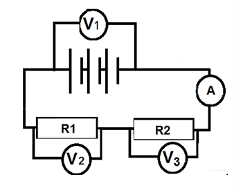
In this circuit in Figure 9, the voltage across the battery [latex]\scriptsize {{\text{V}}_{{1\text{ }}}}=\text{ 20 V}[/latex].
If the resistors [latex]\scriptsize \text{R1}[/latex] and [latex]\scriptsize \text{R2}[/latex] are of equal resistance, the voltmeters would read as follows: [latex]\scriptsize {{\text{V}}_{2}}=\text{ 10 V }\text{ and }{{\text{V}}_{{3\text{ }}}}=\text{ 10 V}[/latex]
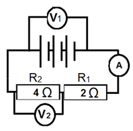
However, if the resistances were different, for example, if [latex]\scriptsize \text{R1 = 1 }\Omega , \text{ and }\text{ R2 = 3 }\Omega[/latex] then the voltage provided by the battery is shared in proportion to the resistance.
The resistance ratio is [latex]\scriptsize \text{1 : 3}[/latex], therefore the voltage will be [latex]\scriptsize {{\text{V}}_{2}}\text{ = 5 V }\text{ and }{{\text{V}}_{3}}\text{ = 15 V}[/latex]
Exercise 3.2
Study the following circuit:
If the voltmeter [latex]\scriptsize {{\text{V}}_{1}}\text{ = 12V}[/latex], determine the reading on voltmeter [latex]\scriptsize {{\text{V}}_{2}}[/latex].
The full solutions are at the end of the unit.
Note
You can consolidate the concepts covered in this unit by watching this video called Voltage explained by The Engineering Mindset (Duration: 10.51).

Summary
In this unit you have learnt the following:
- Electrical potential difference is what makes the charge move in an electric circuit.
- Potential difference (voltage) is defined as the work done per unit charge.
- Emf (electromotive force) is the total possible amount of work done per unit charge by the battery. It will be more than the work done by a unit of charge once it leaves the battery as energy is used to drive charge out of the battery itself.
- Batteries are portable sources of potential difference.
- Power stations create potential difference using magnetism and motion.
- Cells connected in series increase the potential difference of the battery.
- Cells connected in parallel do not increase the voltage, but the battery will last longer.
- When resistors are connected in series, the voltage of the battery is shared between them. The sum of the individual voltages across resistors will be equal to the voltage of the battery.
- When resistors in series have equal resistance, the battery voltage is shared equally between them.
- When resistors in series have different resistance, the battery voltage is shared in the same ratio as the resistance.
- When resistors are connected in series, the current is the same everywhere in the circuit.
Unit 3: Assessment
Suggested time to complete: 20 minutes
- Define voltage.
- Explain the difference between emf and the voltage reading across a battery in a closed circuit.
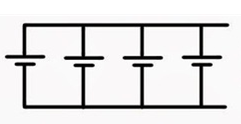
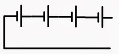
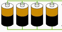
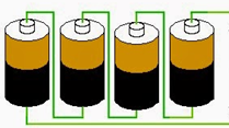
- Identify the type of arrangement of the cells in the batteries illustrated in the diagrams below:
- .
- .
- .
- In a series circuit, one resistor has a voltage of [latex]\scriptsize \text{2 V}[/latex], another [latex]\scriptsize \text{8 V}[/latex] and a third of [latex]\scriptsize 10\text{ V}[/latex]. What is the voltage across the battery?
- If the voltage across a battery in a series circuit of three resistors is [latex]\scriptsize \text{24 V}[/latex] and the voltage across one resistor is [latex]\scriptsize \text{12 V}[/latex]:
- What is the total voltage across the other two resistors?
- If the other two resistors are identical, what is the voltage across each one?
- What is the ratio of the resistances of the three resistors?
- Study the circuit below which has two light bulbs as resistors, A and B.
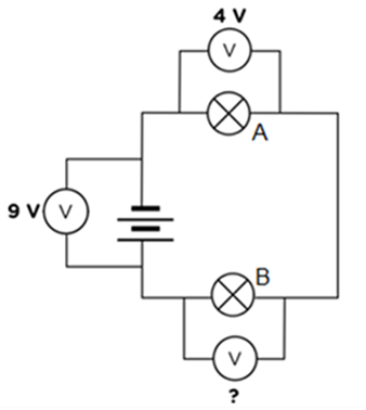
- What is the reading on the voltmeter across light bulb B?
- What would happen to the reading on the voltmeter across the battery if light bulb A was removed, leaving a gap in the circuit. Explain your answer.
- What would the reading be on the voltmeter across light B, if light bulb A was removed and the wires reconnected?
The full solutions are at the end of the unit.
Unit 3: Solutions
Exercise 3.1
- [latex]\scriptsize 9\text{ V}[/latex] ([latex]\scriptsize {{\text{V}}_{{\text{battery}}}}\text{ = }{{\text{V}}_{{\text{cell 1}}}}\text{ + }{{\text{V}}_{{\text{cell 2}}}}\text{ + }{{\text{V}}_{{\text{cell 3}}}}\text{ }...[/latex])
- [latex]\scriptsize 1.5\text{ V}[/latex] (cells in parallel give a battery with a voltage equivalent to one cell)
- .
- [latex]\scriptsize 2\text{ V}[/latex] (cells in parallel)
- [latex]\scriptsize 8\text{ V}[/latex] (cells in series)
Exercise 3.2
The resistors are in series, therefore the voltage of the battery is shared in proportion to their resistance:
[latex]\scriptsize \begin{align*}{{\text{R}}_{\text{1}}}:\text{ }{{\text{R}}_{2}}\text{ = 2 : 4 = 1 : 2}\\\text{Voltage of 12 V will be shared in the ratio 1 : 2}\\{{\text{V}}_{2}}\text{ = 8 V}\end{align*}[/latex]
Unit 3: Assessment
- Voltage is the work done per unit of charge.
- The emf will be higher than the voltage reading across the battery. This is because the emf is the total possible work done per unit charge. Some work is done to drive the charges out of the battery, so by the time they leave the battery they will already have done some work and the potential difference (voltage) will be less.
- .
- parallel (all the positive terminals are connected together, and all the negative terminals are connected together.)
- series (the positive terminal of the first cell is connected to the negative terminal of the next cell, and so on)
- .
[latex]\scriptsize \begin{align*}{{\text{V}}_{{\text{battery}}}} & \text{ = }{{\text{V}}_{{\text{resistor1}}}}+\text{ }{{\text{V}}_{{\text{resistor 2}}}}+\text{ }{{\text{V}}_{{\text{resistor 3}}}}\\ & \text{ = 2 + 8 + 10}\\ & \text{ = 20 V}\end{align*}[/latex] - .
- .
[latex]\scriptsize \begin{align*}{{\text{V}}_{{\text{battery}}}} & \text{ = }{{\text{V}}_{{\text{resistor1}}}}+\text{ }{{\text{V}}_{{\text{resistor 2}}}}+\text{ }{{\text{V}}_{{\text{resistor 3}}}}\\24 & \text{ = 12 + }{{\text{V}}_{{\text{resistor 2}}}}+\text{ }{{\text{V}}_{{\text{resistor 3}}}}\\{{\text{V}}_{{\text{resistor 2}}}}+\text{ }{{\text{V}}_{{\text{resistor 3}}}} & \text{ = 12 V}\end{align*}[/latex] - .
[latex]\scriptsize \begin{align*}12\text{ V shared between two identical resistors}\\\displaystyle \frac{{12}}{2}\text{ = 6 V}\end{align*}[/latex] - .
[latex]\scriptsize \begin{array}{l}\text{Total Voltage = 24 V}\\ \text{Voltage ratio = 12 : 6 : 6 = 2 : 1 : 1}\\ \text{Therefore resistance ratio will be 2 : 1 : 1} \end{array}[/latex]
- .
- .
- .
[latex]\scriptsize \begin{align*}{{\text{V}}_{{\text{battery}}}} & \text{ = }{{\text{V}}_{\text{A}}}+\text{ }{{\text{V}}_{\text{B}}}\\\text{ 9 } & = \text{ 4 + }{{\text{V}}_{\text{B}}}\\\text{ }{{\text{V}}_{\text{B}}} & = \text{ 9 - 4 = 5 V}\end{align*}[/latex] - It would have a slightly higher reading than [latex]\scriptsize 9\text{ V}[/latex]. This is because a voltmeter across a battery in an open circuit will read the emf.
- [latex]\scriptsize 9\text{ V}[/latex]. Light bulb B will be the only resistor in the circuit so it will get the total potential difference supplied by the battery as it does not have to share with any other resistor.
- .
Media Attributions
- img01(b)_Figure1 © Siyavula is licensed under a CC BY-NC-ND (Attribution NonCommercial NoDerivatives) license
- img01(a)_Figure1 © Siyavula is licensed under a CC BY-NC-ND (Attribution NonCommercial NoDerivatives) license
- img02_Figure2 © Siyavula is licensed under a CC BY-NC-ND (Attribution NonCommercial NoDerivatives) license
- img03_Figure3 © L Kleynhans is licensed under a CC BY (Attribution) license
- QR_Code_PSL2SO43U3_2
- img04_Figure4 © OpenStax is licensed under a CC BY (Attribution) license
- img05_Figure5 © DHET is licensed under a CC BY (Attribution) license
- img06_Figure6 © DHET is licensed under a CC BY (Attribution) license
- img07(a)_Ex3.1Q3 © DHET is licensed under a CC BY (Attribution) license
- img07(b)_Ex3.1Q3 © DHET is licensed under a CC BY (Attribution) license
- img08_Figure7 © Siyavula is licensed under a CC BY-NC-ND (Attribution NonCommercial NoDerivatives) license
- img09_Figure8 © Siyavula is licensed under a CC BY-NC-ND (Attribution NonCommercial NoDerivatives) license
- QR_Code_PSL2SO43U3_3
- img10_Act3.2 © Siyavula is licensed under a CC BY-NC-ND (Attribution NonCommercial NoDerivatives) license
- img11_Figure9 © L Kleynhans is licensed under a CC BY (Attribution) license
- img12_Ex3.2 © L Kleynhans is licensed under a CC BY (Attribution) license
- QR_Code_PSL2SO43U3_1
- img13_AssessmentQ3 © L Kleynhans
- img13_AssessmentQ3 © L Kleynhans is licensed under a CC BY (Attribution) license
- img14_AssessmentQ6 © L Kleynhans is licensed under a CC BY (Attribution) license
the difference in electrical potential between two points
an instrument used to measure potential difference (voltage)
the unit in which potential difference (voltage) is measured
another term for potential difference, the work done per unit charge
the maximum amount of work per coulomb of charge supplied by the battery
when the positive terminal of a cell is connected to the negative terminal of the next cell
when all the positive terminals of different cells are connected together, and all the negative terminals are connected together
when resistors are arranged in one pathway and all charges have to pass through every resistor
