Mechanics: Identify, describe, and apply principles of simple machines and mechanical advantage in everyday contexts
Unit 1: Simple machines
Leigh Kleynhans
Unit 1 outcomes
By the end of this unit you will be able to:
- Describe simple machines.
- Describe the functions of simple machines.
- State the law of simple machines.
- State and identify examples of six basic machines:
- lever
- wheel and axle
- pulley
- inclined plane
- screw
- wedge.
What you should know
Before you start this unit, make sure you can:
- Identify and apply principles of force. See Subject outcome 2.2 to revise this.
- Identify, describe and apply principles of mechanical energy. See Subject outcome 2.3 to revise this.
Introduction
In this unit you will learn what a simple machine is and about the different ways in which simple machines are used to make work easier. Once you understand the principle of a simple machine, you will learn about six different types of simple machines used in everyday applications.
Basic functioning of simple machines
What are simple machines? Simple machines are tools that make work easier. They have few or no moving parts. These machines use energy to do work with one movement. They make our work easier by letting us use less mechanical effort to move an object.
So, we can say that the function of simple machines is to transfer energy by means of doing work. The amount of energy transferred remains constant. However, the machine can change the ratio of the force and distance involved in the energy transfer.
Formula for work or energy transfer: [latex]\scriptsize Work\text{ }or\ Energy=Force\text{ x }distance[/latex]
Simple machines make work easier for us by allowing us to push or pull over increased distances, using the idea of spreading force over distance: if you push further, you can use less force. You are doing the same amount of work — it just seems easier. You move an object a greater distance to accomplish the same amount of work with less force. Simple machines give us an advantage by changing the amount, speed, or direction of forces. They allow us to use a smaller force () over a large distance to overcome a larger force () acting over a smaller distance.
The law of simple machines
The states that the product of the effort force and the distance over which it is applied is equal to the resistance force and the distance over which it acts.
[latex]\scriptsize {{F}_{e}}\text{ x }{{d}_{e}}={{F}_{r}}\text{ x }{{\text{d}}_{r}}[/latex]
The equation shows how a simple machine can achieve the same amount of output work by reducing the amount of effort force and increasing the distance over which the effort force is applied.
Exercise 1.1
- What is the advantage of using simple machines, if they do not reduce the amount of work required?
- What is the difference between the effort force and the resistance force in a simple machine?
- State the law of simple machines in words.
- State the law of simple machines in an equation.
The full solutions are at the end of the unit.
Types of simple machines
There are six different types of simple machines that we use in everyday applications.
Levers
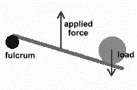
A lever is a board or bar that rests on a turning point. This turning point is called the . The object that a lever moves, is called the . The effort is the applied force you use to move the lever. By changing the position of the fulcrum, you can gain extra power with less effort. The closer the object is to the fulcrum, the easier it is to move. Depending on where the fulcrum is located, a lever can multiply either the force applied or the distance over which the force is applied.
There are three types of levers:
- 1st class levers
- 2nd class levers
- 3rd class levers.
1st class levers
1st class levers have the fulcrum between the load and the effort. The lever changes the direction of the force.
There are three scenarios for 1st class levers.
- A lever with the fulcrum close to the load.
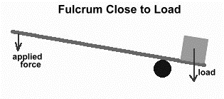
Figure 1: 1st class lever with the fulcrum close to load .
If the fulcrum is placed close to the load, the load can be moved with just a small applied force (effort). This type of lever system gives you a , which means that the force you apply gets multiplied, so a large force acts on the load. The trade-off of using a lever like this is that you have to apply a force over a large distance, and the load itself will move only a short distance. - A lever with the fulcrum exactly halfway between the load and where you apply the force (effort).
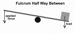
Figure 2: 1st class lever with fulcrum halfway between effort and load .
This lever system has no mechanical advantage. Whatever force is necessary to move the load is the force you must apply. This type of lever system takes advantage of another property of some levers: they reverse the direction of the force. You can push in one direction, and the load moves the other way. - A lever where the fulcrum is nearer the applied force (effort).
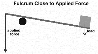
Figure 3: 1st class lever with fulcrum close to effort .
In this scenario, much more force than the weight of the load itself must be applied. If you are lifting something, it will require much more force than would be needed if you were to just lift the load by yourself – this type of lever system makes the work harder. This type of lever system usually uses a motor to lift the load. The advantage is the load is far away, and it moves a long distance.
Examples of 1st class levers are:
- a see-saw
- scissors
- pliers.
2nd class levers
2nd class levers have the load in the centre; between the fulcrum and the applied force or effort.
This lever causes the load to move in the same direction as the force applied. When the load is nearer to the fulcrum, the effort needed to lift the load will be less. If you want to move a very large load with a small effort, you must put the load very close to the fulcrum.
Examples of 2nd class levers are:
- a wheelbarrow
- nutcracker.
3rd class levers
In 3rd class levers, the applied force or effort is in the centre; between the load and fulcrum.
This lever system does not give any mechanical advantage. No matter where you apply the force, the force you apply must always be greater than the force of the load. No matter how close or how far the load is from the fulcrum, the effort used to lift the load, has to be greater than the load. The load moves in the same direction as the force you apply. A motor is usually used with this lever system to lift loads at a distance.
Examples of 3rd class levers:
- a bent arm
- a fishing rod.
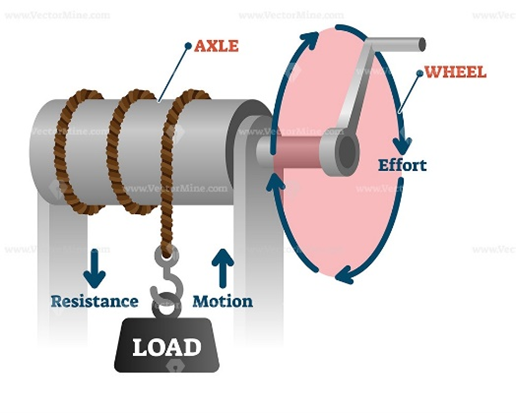
Wheels and axles
The second type of simple machine is the wheel and axle. A wheel with a rod through it, called an axle, can lift or move loads. The axle allows the wheel to turn. The wheel and axle system can be used as a tool to multiply the force you apply or to multiply the distance travelled. There is rotation through a complete circle ([latex]\scriptsize {{360}^{o}}[/latex]). The circle turned by the wheel is much larger than the circle turned by the axle. The increased distance over which the force is applied as the wheel turns results in a more powerful force on the axle, which moves a shorter distance.
Examples of wheels and axles:
- cars
- roller skates
- door handles
- gears.
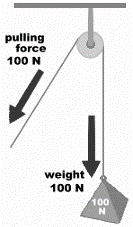
Pulleys
A pulley is a variation of the wheel and axle. Instead of an axle, the wheel rotates on a rope or cord. In a pulley, a cord fits in a groove in the wheel. As the wheel rotates, the cord moves in either direction. When a hook is attached to the rope you can use the wheel’s rotation to raise and lower objects. The rope is attached to the load and when you pull on one side of the pulley system, the wheel turns and the load will move. Pulleys allow you move loads up, down, or sideways. Pulleys are good for moving objects to hard-to-reach places. A pulley makes work seem easier because it changes the direction of motion to work with gravity. The force required to lift the load remains the same as lifting it without the pulley but pulleys have many advantages. For example, it is much easier to raise a flag from the ground, instead of climbing up the pole.
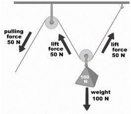
A pulley saves the most effort when you have more than one pulley working together. Two or more pulleys connected together allow a heavy load to be lifted with less force. The main advantage of this pulley combination is that the amount of effort is less than half of the load.
Examples of pulleys are:
- flag poles
- masts on sailboats
- window blinds
- building cranes.
Inclined planes or ramps
An inclined plane is a flat surface that is higher on one end and connects a lower level to a higher level. Inclined planes or ramps make the work of moving things easier, as they allow an object to be raised with less effort than if lifted directly upward. You need less force to move objects to a higher lever using an inclined plane.
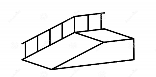
An inclined plane works to reduce effort by increasing the distance over which the load must be moved. The longer the distance of the ramp, the easier it is to do the work. It will, however, take a longer time to do the work.
Examples of inclined planes are:
- ramps
- slanted roads
- paths up a hill
- slides.
Screws
A screw has ridges and is not smooth like a nail. Screws can be used to lower and raise things or to hold things together. A screw is like a long ramp as the thread is similar to a continuous inclined plane. The wider the thread of a screw, the harder it is to turn it. The distance between the threads determines the slope of the inclined plane; and the steeper the slope, the wider the thread. Screws with less distance between the threads are easier to turn.

Examples of screws are:
- jar or bottle lids
- light bulbs
- clamps
- car jacks
- wrenches
- adjustable chairs and stools
- spiral staircases.
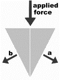
Wedges
A wedge is a simple machine used to push two objects apart. A wedge is usually made up of two inclined planes. These planes meet and form a sharp edge. This edge can split or push objects apart. A wedge can also be used as a lifting device, by forcing it under an object. Most wedges (but not all) are combinations of two inclined planes but they can also be round, like the tip of a nail. The narrower the wedge (or the sharper the point of a wedge), the easier it is drive it in and push things apart.
Examples of wedges are:
- knives
- axes
- teeth
- forks
- nails.
Note
Watch this video to find out more about the use of simple machines in everyday life (Duration: 03.00).
Summary
In this unit you have learnt the following:
- A simple machine is a device used to reduce the mechanical effort required to move objects.
- The principle of simple machines is based on the relationship between force and distance to do a fixed amount of work: the greater the distance, the less force required.
- Mechanical advantage is the amount of effort saved when using a machine.
- Simple machines use mechanical advantage to multiply force.
- There are six types of simple machines used in everyday life:
- A lever – using a rod or board to increase or change the direction of the force on the load.
- A wheel and axle – a rod fixed to the centre of a wheel to increase force on the load.
- A pulley – a rope that passes over a grooved wheel to change direction of the force on the load, or when used in combinations to reduce the applied force required.
- An inclined plane – increases the distance and thereby reduces the effort to raise a load from a low level to a higher level.
- A screw – a spiral inclined plane, it can keep objects together or raise and lower a platform.
- A wedge – two back-to-back inclined planes used to redirect the applied force and split something apart.
Unit 1: Assessment
Suggested time to complete: 10 minutes
- Match the simple machine with its correct definition by writing the corresponding number in the answer column.
Simple machine Advantage - Lever
- Large rotation can increase force on a smaller rotation
- Inclined plane
- Reduces effort to raise or lower a load vertically
- Wedge
- Reduces the effort to raise an object from a low level to a high level by increasing the distance
- Screw
- Uses a rope to change the direction of the force
- Wheel and axle
- Increases the force on the load
- Pulley
- Can split an object apart
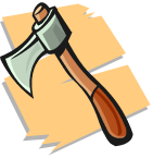
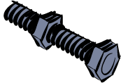
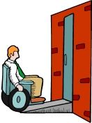
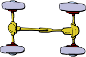
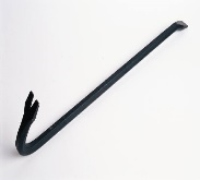
- Identify the type of simple machine in each picture:
- .

The full solutions are at the end of the unit.
Unit 1: Solutions
Exercise 1.1
- Simple machines make the work easier by changing the ratio of the force and the distance
- The effort force is the input force applied to the machine and the resistance force is the weight of the object that has to be moved.
- Simple machines transfer energy but allow the use of a smaller force (the effort force) over a large distance to overcome a larger force (resistance force) acting over a smaller distance. In this way they make the work easier.
.
The law of simple machines states that the product of the effort force and the distance over which it is applied is equal to the resistance force and the distance over which it is applied. [latex]\scriptsize {{F}_{e}}\text{ x }{{d}_{e}}={{F}_{r}}\text{ x }{{d}_{r}}\text{ }[/latex]4.
Unit 1: Assessment
- .
- 5
- 3
- 6
- 2
- 1
- 4
- .
- lever
- wheel and axle
- lever, wheel and axle
- wedge
- screw
- inclined plane
- wheel and axle
- pulley
- lever
Media Attributions
- img03_Figure3 © L Kleynhans is licensed under a CC BY (Attribution) license
- img02_Figure2 © L Kleynhans is licensed under a CC BY (Attribution) license
- img01_Figure1 © L Kleynhans is licensed under a CC BY (Attribution) license
- img04_Figure4 © L Kleynhans is licensed under a CC BY (Attribution) license
- img05_Figure5 © L Kleynhans is licensed under a CC BY (Attribution) license
- img06_Figure6 © L Kleynhans is licensed under a CC BY (Attribution) license
- img07_Figure7 © L Kleynhans is licensed under a CC BY (Attribution) license
- img08_Figure8 © L Kleynhans is licensed under a CC BY (Attribution) license
- img09_Figure9 © L Kleynhans is licensed under a CC BY (Attribution) license
- img10_Figure10 © L Kleynhans is licensed under a CC BY (Attribution) license
- img11_Figure11 © L Kleynhans is licensed under a CC BY (Attribution) license
- img12(a)_AssessmentQ2_ © L Kleynhans is licensed under a CC BY (Attribution) license
- img12(b)_AssessmentQ2 © L Kleynhans is licensed under a CC BY (Attribution) license
- img12(c)_AssessmentQ2 © L Kleynhans is licensed under a CC BY (Attribution) license
- img12(d)_AssessmentQ2 © L Kleynhans is licensed under a CC BY (Attribution) license
- img12(e)_AssessmentQ2 © L Kleynhans is licensed under a CC BY (Attribution) license
- img12(f)_AssessmentQ2 © L Kleynhans is licensed under a CC BY (Attribution) license
- img12(g)_AssessmentQ2 © L Kleynhans is licensed under a CC BY (Attribution) license
- img12(h)_AssessmentQ2 © L Kleynhans
- img12(i)_AssessmentQ2 © L Kleynhans is licensed under a CC BY (Attribution) license
the force placed on the simple machine (also called the applied force or input force)
the force needed to move the load
the product of the effort force and the distance over which this force is applied is equal to the product of the resistance force and the distance over which this force acts
the point on which a lever will turn
the weight being lifted by the simple machine
the amount of effort saved when using a machine
