Waves, sound and light: Identify, describe and apply principles of geometrical optics in everyday contexts
Unit 2: More on reflection of light
Linda Pretorius
Unit outcomes
By the end of this unit you will be able to:
- Draw diagrams showing reflection with reference to plane, concave and convex mirrors, indicating for each diagram:
- the angle of incidence
- the angle of reflection
- the type and size of the image and the distance at which it is formed.
What you should know
Before you start this unit, make sure you can:
- Describe what reflection is, as covered in Subject outcome 3.2, Unit 1.
- State the law of reflection, as covered in Subject outcome 3.2, Unit 1.
- Interpret a diagram showing reflection, as covered in Subject outcome 3.2, Unit 1.
Introduction
In this unit you will learn how the principle of reflection applies to mirrors. You will also learn to draw ray diagrams to understand how images are formed by different types of mirrors.
An introduction to mirrors and images
We see mirrors all around us in everyday life. A mirror is useful to check whether we look neat before we go out, or to shave or put on make-up in the bathroom. In a car, rear-view and side mirrors help us to see what is happening on the road behind us. We also use mirrors in alleys, hallways or on the corner of roads to show oncoming traffic. We use mirrors even in space, and to understand more about the universe. Telescopes, such as the Southern African Large Telescope in Sutherland and the Hubble Space Telescope, use mirrors to reflect and focus light.
A mirror is a shiny, polished surface that reflects light to produce a representation of an object, called an . An image is formed at a point in space where all the light rays reflecting off the mirror’s surface intersect, or appear to intersect.
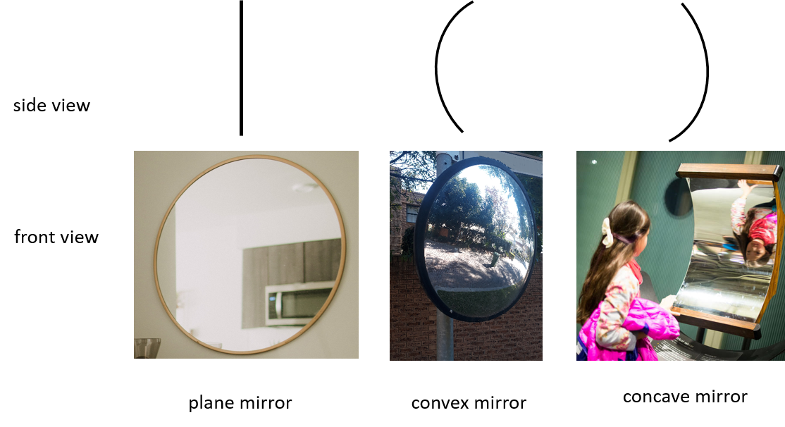
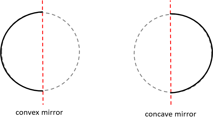
There are different types of mirrors (see Figure 1). A mirror with a flat surface is called a plane mirror. In contrast, the reflective surface of a spherical mirror is curved, and can be either concave or convex. In a , the reflective surface bulges inwards; in a , it bulges outwards. Figure 2 shows that you can understand a curved mirror as a section cut from a sphere (ball), and then silvered either on the inside to form a concave mirror, or on the outside to form a convex mirror.
As you will learn from drawing ray diagrams, mirrors can also be described as or based on the way they cause light rays to reflect. Plane mirrors and convex mirrors always cause light rays to diverge; concave mirrors can cause light rays to converge or diverge.
Different types of mirrors form different types of images, which we can describe according to the following characteristics:
- The location of the image – in other words where the image appears to form relative to the reflective surface, and can either be virtual or real. A appears to form from behind the mirror, which is a virtual (non-real) space. In contrast, a appears to form in front of the mirror, and therefore in a real (actual) space.
- The size of the image can be bigger or smaller than the object. An image that is bigger than the object is magnified; an image that is smaller than the object is reduced.
- The orientation of the image can be upright or inverted (upside down).
Activity 2.1: Observe an image formed by a plane mirror
Time required: 5 minutes
What you need:
- a flat reflective surface, such as a bathroom mirror
- a sheet of white paper and a marker pen
- a ruler
- an object of which the top and bottom, and left and right side can be seen clearly (e.g. a small cup).
What to do:
- Set a plane mirror up against a wall or upright support.
- Measure out a distance from the edge of the paper to where you will place the object (e.g. [latex]\scriptsize 10\text{ cm}[/latex]). Draw a line along the length of this distance on the paper.
- Place the paper in front of the mirror, with the edge from where you drew the line close to but not touching the edge of the mirror.
- Put the object behind the line.
- Describe the image you see in the mirror:
- Where does the image appear to form: behind or in front of the mirror?
- Is the image bigger, smaller or the same size as the object?
- Is the image upright or inverted?
- Is the horizontal orientation (in other words, the left and right side) the same in the image as in the object?
What did you find?
- The image appears to be at a point behind the mirror, at the same distance as the object. It is a virtual image.
- The image is upright and it is the same size as the object.
- The left and right sides of the object appear reversed in the image.
Note
If you do not have a mirror to set up the activity described here, go to this simulation to see a similar activity.

Activity 2.2: Observe an image formed by a curved mirror
Time required: 5 minutes
What you need:
- a large, shiny spoon
What to do:
- Look at the back of the spoon. Is the surface convex or concave?
- Hold the back of the spoon in front of your face. Describe the image you see in the spoon with regard to its:
- location
- size
- vertical orientation.
- Move the spoon away from your face. What do you notice?
- Now turn the spoon around so that you have the bowl (hollow side) in front of your face. Start quite close to your face and then gradually move it away from your face. Describe the image you see in the spoon with regard to its:
- location
- size
- vertical orientation.
What did you find?
- Steps 1–3: The back of the spoon represents a convex mirror. Holding it in front of an object creates an image that appears to be located behind the reflective surface. It is therefore a virtual image. The image is upright and smaller than the actual object. The image becomes smaller when the spoon (reflective surface) is moved away from the object. A wide view of the background is visible.
- Step 4: The bowl of the spoon represents a concave mirror. It creates a real, inverted image that is bigger than the object. When the spoon is moved away from the object, the image becomes smaller and remains inverted. If you were able to move it away far enough, the image would become upright and virtual at some point, and then start to enlarge.
Ray diagrams for images formed by mirrors
Ray diagrams are useful to help us understand the characteristics of images formed by mirrors. As you learnt in Unit 1, a ray diagram is a diagram that shows the path of light rays as they interact with an optical surface. In the case of a ray diagram for images formed by reflection off mirrors, we can see at what distance an image will form relative to the reflecting surface and what its characteristics will be.
Although light emanates in all directions from an object when the image is formed, drawing only a few specific rays makes it easier to interpret the diagram. To draw a ray diagram for images formed by mirrors, we always show the:
- object
- reflective surface (mirror)
- incident rays
- reflected rays.
Note that each pair of incident and reflected rays are relative to a specific point on the object.
Take note!
To check yourself when drawing ray diagrams for mirror images, always keep the law of reflection in mind, which states that the angle of incidence is equal to the angle of reflection: [latex]\scriptsize {{\theta }_{\text{i}}}={{\theta }_{\text{r}}}[/latex]
Ray diagrams for images formed by a plane mirror
In Activity 2.1, we saw that the image formed by a plane mirror is always:
- virtual
- upright
- the same size as the object
- formed at the same distance behind the mirror as the object.
Let’s look at an example to see how these characteristics are used when drawing a ray diagram.
Example 2.1
Draw a ray diagram for an image formed by a plane mirror.
Solution
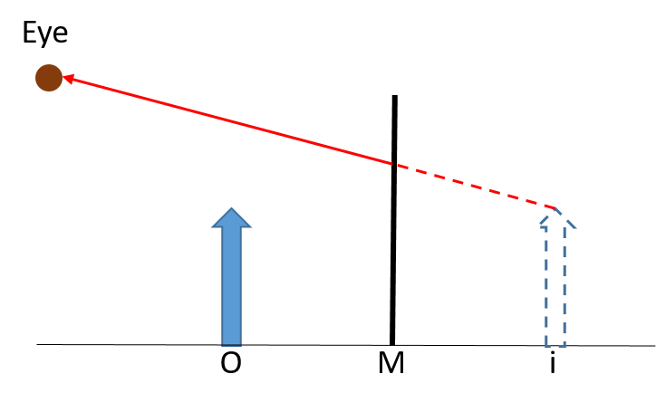
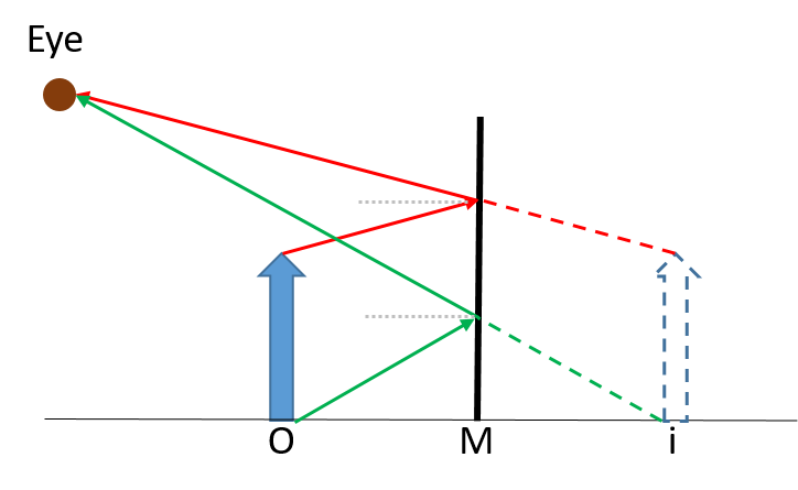
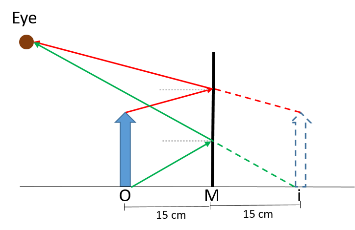
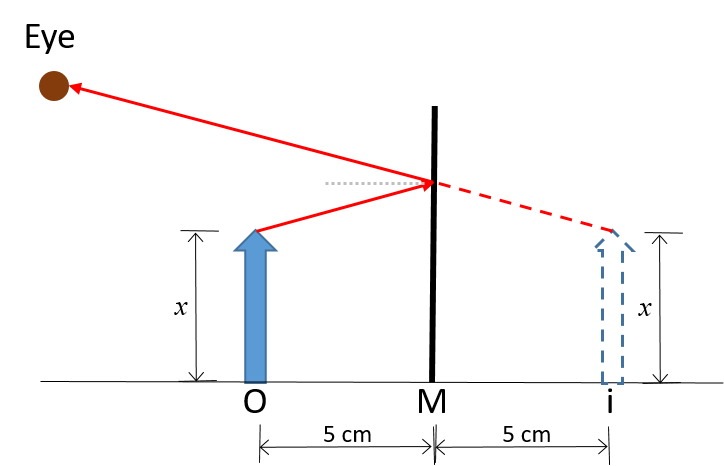
- Start by drawing the mirror, as viewed from the side, and the object placed in front of the mirror. The object is often drawn as an arrow. For the purpose of the example we denote the mirror ‘M’ and the object ‘O’, but these labels do not have to be shown in your diagram.

- We know that a plane mirror always forms a virtual image – that is, an image that forms behind the mirror. We also know that the image formed by a plane mirror is upright, formed at the same distance as the object and is of the same height as the object. We can therefore draw the image behind the mirror accordingly. For the purpose of the example, we denote the image ‘i’. Note that the image is drawn in dashed lines, because it exists in the virtual space.

- An observer is viewing the image, so we know where the would be for each point on the image. Consider the observer looking at the top of the image. We draw a dashed line from the top of the image to the mirror along the line of sight, because the light ray is apparently but not actually coming from that point: it is in the virtual space. The ray on the same side of the mirror as the observer is drawn as a solid line, because it represents the actual light ray reflected off the mirror.
- Having drawn the reflected ray, we can now draw in the incident ray from the top of the object to the mirror. You can check whether you have the directions correct by drawing in a feint normal line and comparing the angle of incidence and angle of reflection: they must be equal.
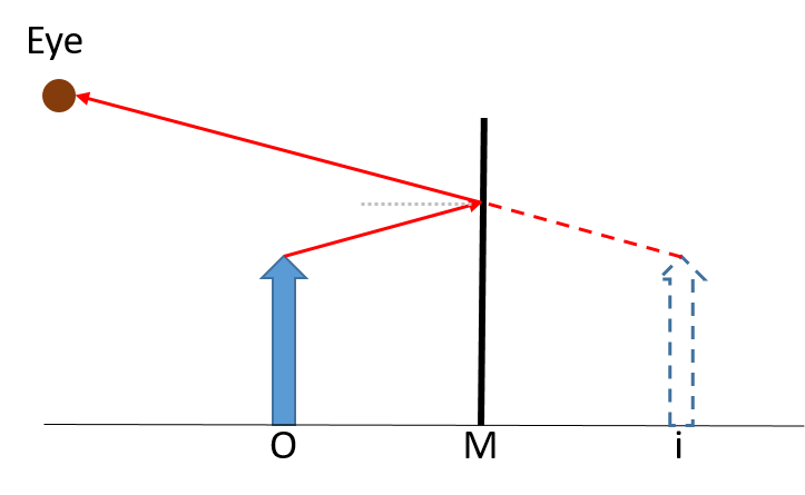
- Repeat the process in steps 3 and 4 for another point on the image, such as the bottom of the image.
Ray diagrams for images formed by curved mirrors
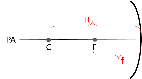
To draw ray diagrams for images formed by curved mirrors, we have to define some terminology first, as shown in Figure 3.
- Centre of curvature (C): The centre of the sphere from which the mirror was cut.
- Radius of curvature (R): The radius of the sphere from which the mirror was cut.
- Principal axis (PA) : An imaginary line that runs through the centre of curvature. It is perpendicular to the mirror at the outer most limit of curvature (this point is also called the pole of the mirror).
- Focal point (F): The point halfway between the centre of curvature and the surface of the mirror. This is the point through which all reflected light rays pass (or appear to pass through, in the case of a diverging mirror).
- Focal length (f): The distance from the focal point to the surface of the mirror.
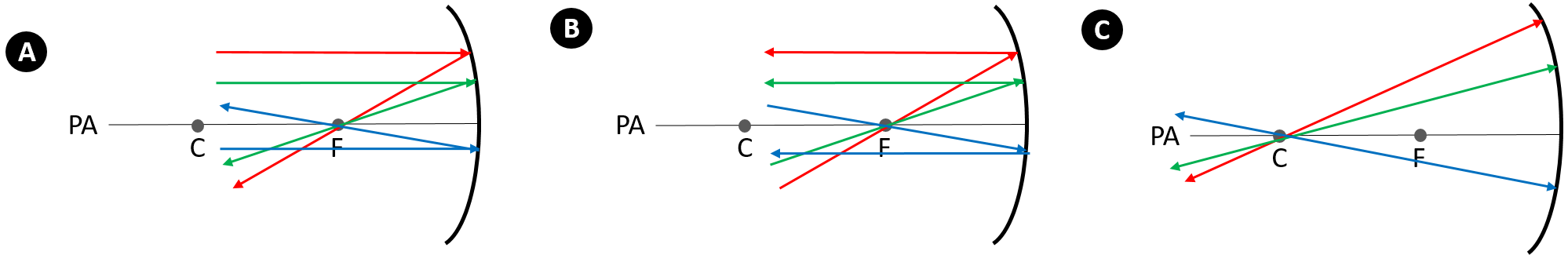
Remember that the law of reflection always holds when light strikes a mirror, regardless of whether the surface is flat or curved. However, when working with curved mirrors, drawing many incident rays and their associated reflected rays at the correct angles can become tricky. For curved mirrors it is therefore useful to remember three general cases that will always apply:
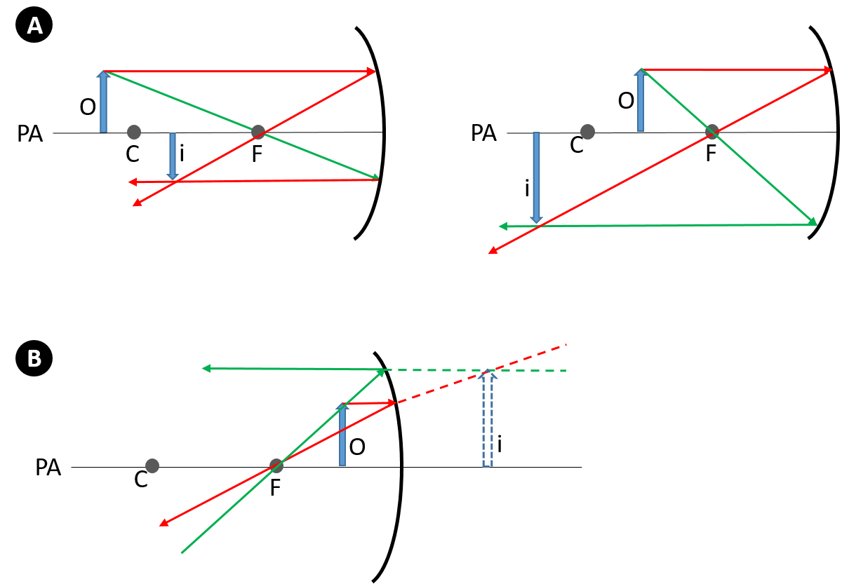
- Any incident ray parallel to the principal axis will be reflected to pass through the focal point (panel A).
- Any incident ray that passes through the focal point will be reflected parallel to the principal axis (panel B).
- Any incident ray that passes through the centre of curvature will be reflected back through the centre of curvature after striking the mirror’s surface (panel C)
We will now look at examples of drawing ray diagrams for both concave and convex mirrors.
Ray diagram for images formed by a concave mirror
The type of image formed by a concave mirror can vary: it can be upright or inverted; real or virtual; magnified or diminished. The type of image formed depends on the position of the object relative to the mirror, which in turn determines whether reflected rays will converge or diverge.
Note
To see how the position of the object affects the image formed by a concave mirror, watch the demonstration called Concave mirror images (Duration: 02.28).

Applying the general principles for drawing a ray diagram for an image formed by a concave mirror will help you understand why different types of images can be formed by concave mirrors.
Example 2.2
Draw a ray diagram to illustrate an image formed by a concave mirror when the object is placed at a point beyond the centre of curvature.
Solution
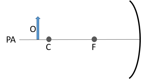
- First draw the basic components of the diagram: the mirror and principal axis (PA), and also the centre of curvature (C) and focal point (F).

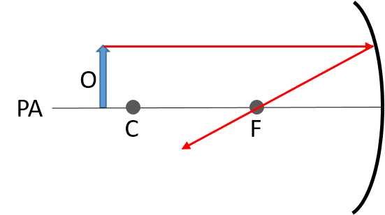
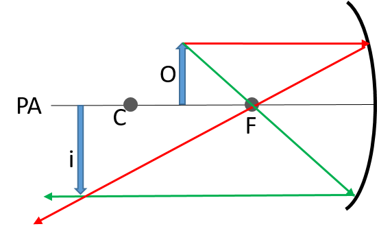
- Draw an arrow to represent the object (O) at a point beyond C.
- Draw an incident ray from a point on the object (e.g. the top) towards the mirror, parallel to the principal axis. Then also draw its associated reflected ray. Remember that any incident ray parallel to the principal axis will be reflected to pass through the focal point.
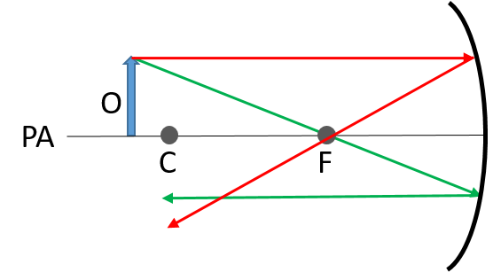
- Draw another pair of rays from the same point on the object, but this time with the incident ray passing through the focal point. Again, remember that any incident ray passing through the focal point will be reflected parallel to the principal axis.
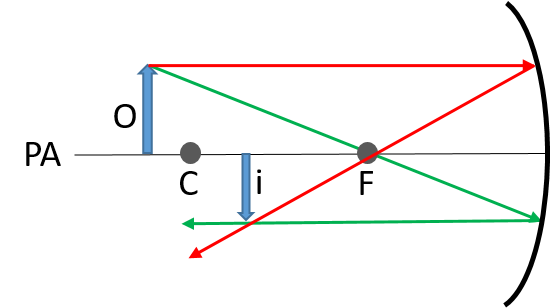
- From the diagram in step 4, we can see that the reflected rays converge. The image (i) will be formed at this point of intersection, which is between the centre of curvature and the focal point. Notice that the image is:
- real (it is formed in front of the mirror)
- inverted
- reduced.
Example 2.3
Draw a ray diagram to illustrate an image formed by a concave mirror when the object is placed between the focal point and the mirror.
Solution
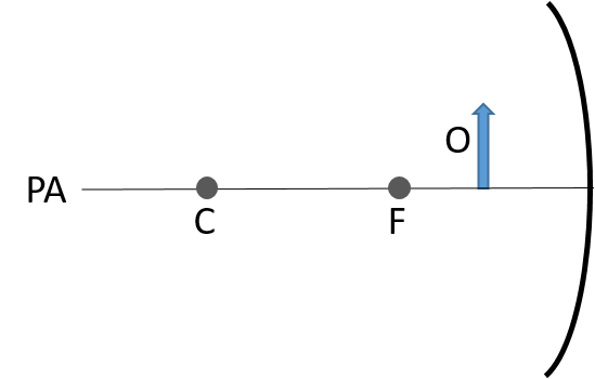
Draw the basic components of the diagram: the mirror and principal axis (PA), and also the centre of curvature (C) and focal point (F).

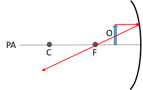
Draw an arrow to represent the object at a position between the focal point and the mirror.
Draw an incident ray from a point on the object (e.g. the top) towards the mirror, parallel to the principal axis. Then also draw its associated reflected ray. Remember that any incident ray parallel to the principal axis will be reflected to pass through the focal point.
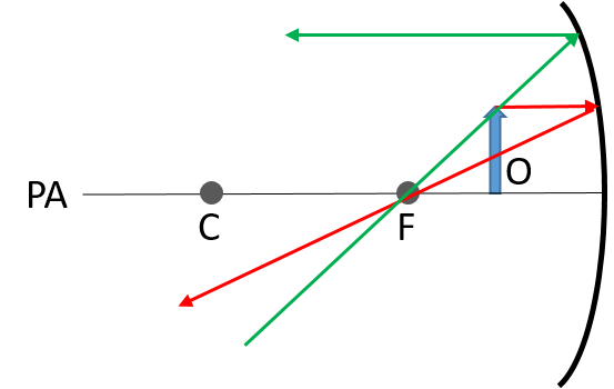
Draw another pair of incident and reflected rays. However, notice that if we were to draw the incident ray passing from the object through the focal point, it would never reach the mirror, and so there would be no reflected ray. A solution is to draw a ray from the object to the mirror, in line with the focal point, and then extending the line backwards. Applying the principle that any incident ray passing through the focal point will be reflected parallel to the principle axis allows us to draw the reflected ray.
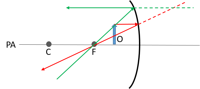
Recall that the image forms at the point where the reflected rays intersect. Yet, looking at the diagram in step 4, we see that the reflected rays do not intersect. However, extending the reflected rays backward, behind the mirror, will lead to a point where they do intersect. Notice that because the extensions of the reflected rays are behind the mirror – that is, in the virtual space – they are drawn as dashed lines.
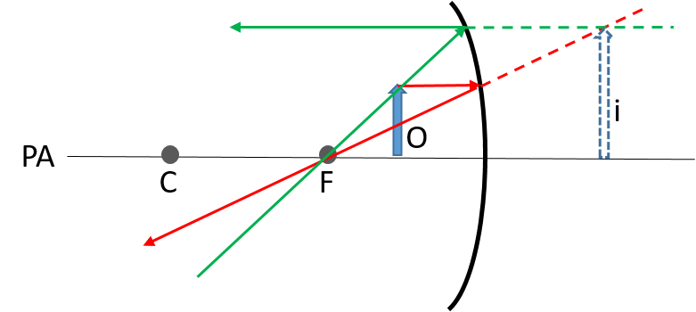
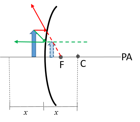
Now draw in the image. The image is virtual, magnified and upright, and you can see that the reflected rays seem to diverge from the image.
Drawing ray diagrams for images of objects placed at various positions in front of a concave mirror will show why concave mirrors form varied images. A special case occurs when the object is placed at the focal point, as shown in Figure 5.
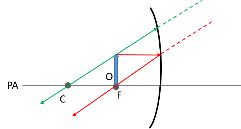
In drawing the ray diagram, we start by drawing an incident ray parallel to the principal axis and then its reflected ray passing through the focal point. The second set of rays can be drawn using the general principle that any incident ray passing through the centre of curvature will be reflected along the same path. Extending the reflected rays backwards shows that they remain parallel; they will never intersect. That means, no image will be formed.
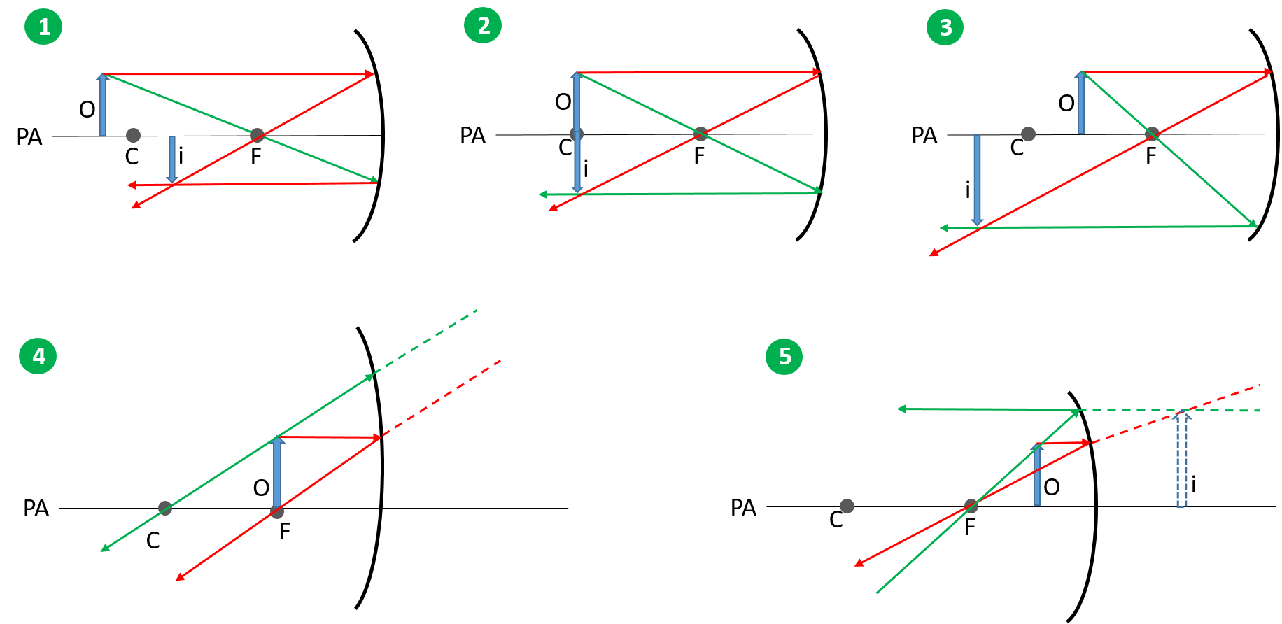
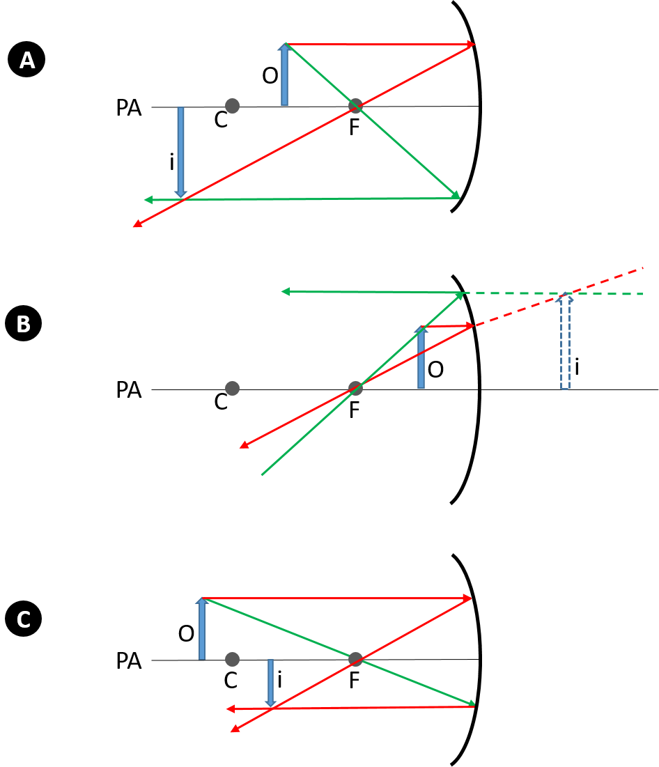
The images formed by a concave mirror when an object is placed at various positions in front of the mirror can be summarised as follows , with the ray diagram for each case shown below:
| Object position | Image position | Image type | Image size | Image orientation |
| 1. Beyond C | Between C and F | Real | Reduced | Inverted |
| 2. At C | At C | Real | Equal to size of object | Inverted |
| 3. Between C and F | Beyond C | Real | Magnified | Inverted |
| 4. At F | No image formed | |||
| 5. Between F and mirror | Behind mirror, at a distance that corresponds to a point between C and F | Virtual | Magnified | Upright |
Note
To explore ray diagrams for concave mirrors interactively, access this simulation. Set the optical surface to ‘mirror’. Note that the point labelled 2f is the same as the centre of curvature (C) in the diagrams shown in this unit.

Ray diagram for images formed by a convex mirrors
The general principles for light reflecting off a convex mirror are the same as for a concave mirror:
- Any incident ray that strikes the mirror parallel to its principal axis will be reflected in line with the focal point.
- Any incident ray that strikes the mirror in line with the focal point will be reflected parallel to the principal axis.
However, in the case of a convex mirror, the centre of curvature and the focal point are located behind the mirror, which means reflected rays will diverge. A convex mirror therefore always forms a virtual image that is upright and reduced. You can draw a ray diagram to confirm this.
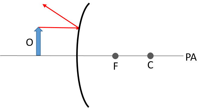
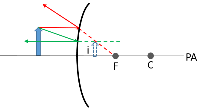
Example 2.4
Draw a ray diagram to illustrate an image formed by a convex mirror.
Solution
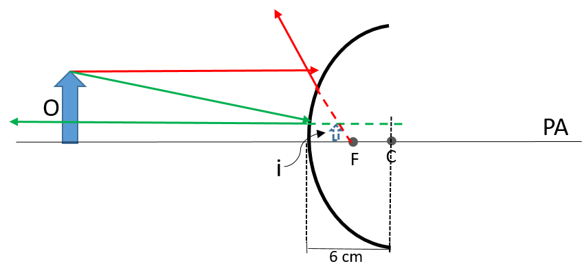
- Draw the basic components of the diagram: the mirror, the principal axis (PA) and the focal point (F), and place the object in front of the mirror.

- Draw an incident ray from a point on the object (e.g. the top) towards the mirror, parallel to the principal axis. Then also draw its associated reflected ray. Remember that any incident ray parallel to the principal axis will be reflected to pass through the focal point. Because the focal point is behind the mirror – that is, in the virtual space – the extension of the reflected ray is drawn as a dashed line.
- Then draw an incident ray headed towards the focal point, and its associated reflected ray. Again, extend the reflected ray backwards. The image forms where the reflected rays intersect. It is a virtual image, reduced and upright.
Exercise 2.1
- Draw a ray diagram to show the image formed of an object that is placed [latex]\scriptsize 15\text{ cm}[/latex] away from a plane mirror. The diagram does not have to be to scale.
- Use a ray diagram to show that a concave mirror forms a magnified image of an object placed between the centre of curvature and the focal point.
- Draw a ray diagram to describe the type of image formed of an object reflected in a shiny Christmas tree bauble. The diameter of the bauble is [latex]\scriptsize \text{6 cm}[/latex] and the object is [latex]\scriptsize \text{20 cm}[/latex] away from the bauble. The diagram does not have to be to scale.
The full solutions are at the end of the unit.
Summary
In this unit you have learnt the following:
- A mirror is a shiny reflective surface that is able to form an image of an object in front of it.
- An image is a representation of an object.
- The image location is the point in space where reflected rays intersect or appear to intersect.
- An image formed by a mirror can be: virtual or real; upright or inverted; magnified or reduced.
- The type of image formed by a mirror depends on the shape of the reflective surface, which can be flat or curved. A mirror with a flat reflective surface is called a plane mirror. Curved mirrors can have a convex or concave shape.
- A flat mirror always forms virtual, upright images that are the same height as the object.
- A convex mirror always forms virtual, upright and reduced images.
- A concave mirror can form varied images, depending on the distance of the object in front of the mirror.
- Ray diagrams are useful to help us understand the characteristics of images formed by mirrors.
- To draw ray diagrams for curved mirrors, the centre of curvature and focal point have to be shown.
- Light emanates in all directions from an object. The law of reflection always holds when light strikes a mirror, regardless of whether the surface is flat or curved.
- To make it simpler to draw ray diagrams for an image formed by a curved mirror, it is useful to remember that the following cases will always hold:
- Any incident ray that travels parallel to the principal axis will be reflected through the focal point.
- Any incident ray that travels through the focal point towards the surface of the mirror will be reflected parallel to the principal axis.
- Any incident ray that travels through the centre of curvature will be reflected back through the centre of curvature.
Unit 2: Assessment
Suggested time to complete: 30 minutes
- The image location of a mirror is:
- the point in space where all incident and reflected rays intersect.
- the point in space where all reflected rays intersect or appear to intersect.
- always in front of the mirror.
- always behind the mirror.
- An object that is [latex]\scriptsize 20\text{ cm}[/latex] high is placed [latex]\scriptsize 60\text{ cm}[/latex] in front of a concave mirror. The mirror has a radius of curvature of [latex]\scriptsize 80\text{ cm}[/latex]. Where would the image of the object be formed?
- [latex]\scriptsize 60\text{ cm}[/latex] in front of the mirror
- Somewhere between [latex]\scriptsize 60\text{ cm}[/latex] and [latex]\scriptsize 80\text{ cm}[/latex] in front of the mirror.
- More than [latex]\scriptsize 80\text{ cm}[/latex] in front of the mirror.
- [latex]\scriptsize 60\text{ cm}[/latex] behind the mirror.
- An object in front of a plane mirror will form an image that is:
- real and magnified.
- virtual and upright.
- virtual and inverted.
- virtual and magnified.
- You see an image formed by a mirror that it inverted and magnified. What type of mirror would form this image?
- a convex mirror
- a concave mirror
- a plane mirror
- a corner mirror
- If the radius of curvature of a convex mirror is [latex]\scriptsize 10\text{ cm}[/latex], its focal point will be:
- [latex]\scriptsize 10\text{ cm}[/latex] behind the mirror.
- [latex]\scriptsize 10\text{ cm}[/latex] in front of the mirror.
- [latex]\scriptsize \text{5 cm}[/latex] in front of the mirror.
- [latex]\scriptsize \text{5 cm}[/latex] behind the mirror.
- .
- Explain why the rear-view mirror of a car uses a curved mirror rather than a plane mirror.
- Would it be better to use a concave or a convex mirror in this application? Give a reason for your answer.
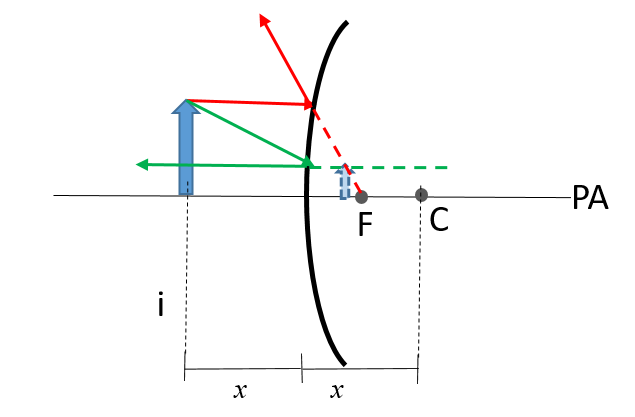
- Draw ray diagrams to compare the images formed by a convex mirror when the same object is placed at a point:
- equal to the radius of curvature in front of the mirror.
- closer to the mirror than the radius of curvature.
- Draw ray diagrams to explain why the image formed by concave mirror can be:
- virtual or real
- magnified or reduced.
- What type of mirror is shown in each of the following photos? Give a reason for your answer in each case.
- .

- .

- .
- Draw a ray diagram to explain what type of image is formed of an object placed [latex]\scriptsize \text{5 cm}[/latex] in front of a plane mirror.
The full solutions are at the end of the unit.
Unit 2: Solutions
Exercise 2.1
- The image will be formed behind the mirror, at the same distance as where the object is placed. The image is virtual and upright, and the same height as the object.
- .
- The image is virtual, reduced and upright.
Unit 2: Assessment
- B.
An image formed by a mirror is due to the reflection of incident rays, and forms at the point where reflected rays intersect (in the case of a real image) or appears to intersect (in the case of a virtual image). - C.
If the radius of curvature is [latex]\scriptsize 80\text{ cm}[/latex], the focal point would be at [latex]\scriptsize 40\text{ cm}[/latex]. An object that is placed at [latex]\scriptsize 60\text{ cm}[/latex] is therefore between the centre of curvature and the focal point, which means the image would be formed beyond the centre of curvature. - B.
A plane mirror always forms virtual, upright images that are the same height as the object. - B.
Convex and plane mirrors always form upright images. A concave mirror can form an inverted magnified image when the object is place between the centre of curvature and the focal point. - D.
The focal point of a curved mirror is midway between the centre of curvature and the surface of the mirror. The focal point of a convex mirror is behind the mirror. - .
- Because a curved mirror allows reduced images to be formed, it can show a wider view than a flat mirror.
- A convex mirror would be better, as it always forms an upright image, whereas the images formed by a concave mirror can be either upright or inverted.
- .
- .
- .
A virtual, upright and reduced image forms in both cases. However, the image size increases to approach the size of the object the closer the object is moved to the surface of the mirror.
- .
- .
- A concave mirror will form real images if the object is placed at any point further than the focal length in front of the mirror (panel A). However, a virtual image will form for an object that is placed at any position between the focal point and the surface of the mirror (panel B).
- A concave mirror will form magnified images if an object is placed at any point between the centre of curvature and the focal point, or between the focal point and the surface of the mirror (panels A and B). A reduced image will form for an object placed at any point beyond the centre of curvature (panel C).
- A concave mirror will form real images if the object is placed at any point further than the focal length in front of the mirror (panel A). However, a virtual image will form for an object that is placed at any position between the focal point and the surface of the mirror (panel B).
- .
- A plane mirror. A virtual, upright image is formed. It appears at the same distance behind the mirror as the object and is of the same height.
- The image is formed by a curved mirror, as can be seen from the somewhat distorted view. We see that the image is upright and reduced. We therefore know that it must be a convex mirror shown here, because when upright images are formed by a concave mirror they are always magnified.
- A plane mirror will form a virtual, upright image of the same height and at the same distance as the object.
Media Attributions
- Img01_Types of mirrors © "Plane mirror: Blake Carpenter Convex mirror: DHET Concave mirror: The Exploratorium, San Francisco" is licensed under a CC BY (Attribution) license
- Img02_Curved mirrors © DHET is licensed under a CC BY (Attribution) license
- QR_Code_PSL2SO32U2_1
- Img03a_Ray diagram_Example2.1 A © DHET is licensed under a CC BY (Attribution) license
- Img03b_Ray diagram_Example2.1 B © DHET is licensed under a CC BY (Attribution) license
- Img03c_Ray diagram_Example2.1 C © DHET is licensed under a CC BY (Attribution) license
- Img03d_Ray diagram_Example2.1 D © DHET is licensed under a CC BY (Attribution) license
- Img03e_Ray diagram_Example2.1 E © DHET is licensed under a CC BY (Attribution) license
- Img04_Characteristics_curved mirror © DHET is licensed under a CC BY (Attribution) license
- Img05_Reflection_curved mirror © DHET is licensed under a CC BY (Attribution) license
- QR_Code_PSL2SO32U2_2
- Img06a_Ray diagram_Example2.2 A © DHET is licensed under a CC BY (Attribution) license
- Img06b_Ray diagram_Example2.2 B © DHET is licensed under a CC BY (Attribution) license
- Img06c_Ray diagram_Example2.2 C © DHET is licensed under a CC BY (Attribution) license
- Img06d_Ray diagram_Example2.2 D © DHET is licensed under a CC BY (Attribution) license
- Img06e_Ray diagram_Example2.2 E © DHET is licensed under a CC BY (Attribution) license
- Img07a_Ray diagram_Example2.3 A © DHET is licensed under a CC BY (Attribution) license
- Img07b_Ray diagram_Example2.3 B © DHET is licensed under a CC BY (Attribution) license
- Img07c_Ray diagram_Example2.3 C © DHET is licensed under a CC BY (Attribution) license
- Img07d_Ray diagram_Example2.3 D © DHET is licensed under a CC BY (Attribution) license
- Img07e_Ray diagram_Example2.3 E © DHET is licensed under a CC BY (Attribution) license
- Img07f_Ray diagram_Example2.3 F © DHET is licensed under a CC BY (Attribution) license
- Img08_Ray diagram_Object at F_concave © DHET is licensed under a CC BY (Attribution) license
- Img09_Ray diagrams_concave_summary © DHET is licensed under a CC BY (Attribution) license
- QR_Code_PSL2SO32U2_3
- Img010a_Ray diagram_Example2.4 A © DHET is licensed under a CC BY (Attribution) license
- Img010b_Ray diagram_Example2.4 B © DHET is licensed under a CC BY (Attribution) license
- Img010c_Ray diagram_Example2.4 C © DHET is licensed under a CC BY (Attribution) license
- Img018_Assessment Q9a © Beazy is licensed under a CC0 (Creative Commons Zero) license
- Img019_Assessment Q9b © Drew Farwell is licensed under a CC0 (Creative Commons Zero) license
- Img011_Exercise 2.1_Q1 answer © DHET is licensed under a CC BY (Attribution) license
- Img012_Exercise 2.1_Q2 answer © DHET is licensed under a CC BY (Attribution) license
- Img013_Exercise 2.1_Q3 answer © DHET is licensed under a CC BY (Attribution) license
- Img014_Assessment Q7a_answer © DHET is licensed under a CC BY (Attribution) license
- Img015_Assessment Q7b_answer © DHET is licensed under a CC BY (Attribution) license
- Img016_Assessment Q8a_answer © DHET is licensed under a CC BY (Attribution) license
- Img017_Assessment Q8b_answer © DHET is licensed under a CC BY (Attribution) license
- Img020_Assessment Q10_answer © DHET is licensed under a CC BY (Attribution) license
a representation of an object
a curved mirror with the reflective surface bulging inwards
converge: to come together at a point
a curved mirror with the reflective surface bulging outwards
diverge: to move out from a single point
to come together at a point
to move out from a single point
an image that appears to originate from a point behind a mirror and which cannot be projected onto a screen
an image that can be projected onto screen
the line along which an observer is looking to view an image
