Mechanics: Identify, describe, and apply principles of simple machines and mechanical advantage in everyday contexts
Unit 2: The concept of mechanical advantage
Leigh Kleynhans
Unit outcomes
By the end of this unit you will be able to:
- Define ideal mechanical advantage (IMA) as the ratio between the distance through which the effort force moves an object and the distance through which the resistance force moves an object: IMA = distance effort F moves ÷ distance resistance F moves.
- Use the law of simple machines in calculations.
- Draw diagrams of a lever where:
- the fulcrum is between the resistance force and the effort force
- the resistance force is between the fulcrum and the effort force
- the effort force is between the fulcrum and the resistance force.
- Calculate mechanical advantage of levers.
What you should know
Before you start this unit, make sure you can:
- Identify and apply principles of force, specifically the calculation of weight (Fg) from mass, as covered in Subject outcome 2.2.
- Identify, describe and apply principles of mechanical energy, as covered in Subject outcome 2.3.
- Identify levers as simple machines, as covered in Subject outcome 2.4, Unit 1.
Introduction
The amount of effort saved when using machines is called (MA). Simple machines use mechanical advantage as a key property to their functionality, helping humans perform tasks that would require more force than a person could produce. We will use the lever as an example of a simple machine to illustrate the concept of mechanical advantage.
Effort force and resistance force
When levers are used as simple machines, the input force that is applied to the lever is referred to as the effort force. The load that is being lifted has weight and the force required to move the object is referred to as the resistance force.
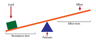
Applying the law of simple machines to levers
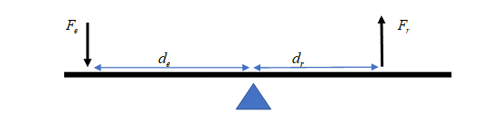
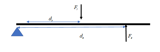
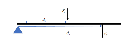
The law of simple machines states that the product of the effort force and the distance over which it is applied is equal to the resistance force and the distance over which it is applied. [latex]\scriptsize {{F}_{e}}\text{ x }{{d}_{e}}={{F}_{r}}\text{ x }{{d}_{r}}\text{ }[/latex]
where:
[latex]\scriptsize {{F}_{e}}[/latex] is the effort force
[latex]\scriptsize {{F}_{r}}[/latex] is the resistance force
[latex]\scriptsize {{d}_{e}}[/latex] is the distance the effort force moves
[latex]\scriptsize {{d}_{r}}[/latex] is the distance the resistance force moves
Mass and weight force are directly proportional, therefore masses can be substituted into this formula instead of forces, depending on what is given in the question.
When this law is applied to levers, the distance the effort moves ([latex]\scriptsize {{d}_{e}}[/latex]) and the distance the resistance force moves ([latex]\scriptsize {{d}_{r}}[/latex] ) are proportional to the distance the effort is from the fulcrum and the distance the load is from the fulcrum. This formula, therefore, allows us to calculate where to place a load relative to the position of the effort to balance a lever.
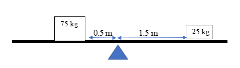
Example 2.1
An adult of [latex]\scriptsize 75\text{ kg}[/latex] sits [latex]\scriptsize 0.5\text{ m}[/latex] from the fulcrum of a seesaw. How far from the fulcrum should a child of [latex]\scriptsize 25\text{ kg}[/latex] sit to keep the seesaw balanced? Draw a diagram to support your reasoning.
Solution
Step 1: Check the units; the units of [latex]\scriptsize F[/latex] and [latex]\scriptsize d[/latex] must be the same
Masses must both be in kg.
Answer for distance will be in m.
Step 2: Wite down the formula
[latex]\scriptsize {{F}_{e}}\text{ x }{{d}_{e}}={{F}_{r}}\text{ x }{{d}_{r}}\text{ }[/latex]
Step 3: Substitute the values and calculate your answer
[latex]\scriptsize \begin{array}{l}\text{75 x 0}\text{.5 = 25 x }{{d}_{r}}\\\text{ }{{d}_{r}}\text{=1}\text{.5 m }\end{array}[/latex]
Step 4: Draw a diagram to support your answer
A seesaw is a 1st class lever, so the fulcrum is between the effort and the load.
Activity 2.1: Practise using the law of simple machines
Time required: 10 minutes
What you need:
- internet access
What to do:
- Go to the PhET Simulation ‘Balancing Act’.

- Load the simulation and go to Balance Lab.
- Check the rulers box. Move the slider to the right, as indicated in the screenshot below.
- Place your ‘load’ of a [latex]\scriptsize 5\text{ kg}[/latex] brick on the left side at [latex]\scriptsize 1.25\text{ m}[/latex].
- Place a [latex]\scriptsize 5\text{ kg}[/latex]brick on the right side until the lever is balanced.
- Measure the effort arm’s distance.
- Remove each of the bricks.
- Place your ‘load’ of a [latex]\scriptsize 20\text{ kg}[/latex] brick on the left side at [latex]\scriptsize 1.25\text{ m}[/latex].
- Place a [latex]\scriptsize 5\text{ kg}[/latex] brick on the right side until the lever is balanced.
- Measure the effort arm’s distance.
- Think about the following:
- Is the lever in the simulation a first, second, or third class lever? Explain how you know.
- Was the distance for a small weight in Step 9 greater than, less than, or equal to the distance for the large weight? Why?
- When the lever was balanced, how did the force x distance of the effort compare to the force x distance of the resistance?
- Now play the game to consolidate the concept.
What did you find?
- In order to balance a mass on a seesaw, an equal mass can be placed an equal distance from the fulcrum on the other side.
- If a smaller mass is used to balance a larger mass, it must be placed further from the fulcrum.
- If a larger mass is used to balance a smaller mass, it must be placed closer to the fulcrum.
- These results support the law of machines: [latex]\scriptsize {{F}_{e}}\text{ x }{{d}_{e}}={{F}_{r}}\text{ x }{{d}_{r}}[/latex].
- The lever in the simulation is a 1st class lever because the fulcrum is between the effort and the load.
Drawing diagrams of levers
The law of simple machines can be applied to all three classes of levers. Always draw a diagram to assist you with the calculations:
1st class lever – fulcrum is between the effort and the load e.g. a seesaw:
2nd class lever – the load is between the effort and fulcrum e.g. wheelbarrow:
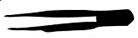
3rd class lever – the effort is between the fulcrum and the load e.g. tweezers:
Exercise 2.1
- A [latex]\scriptsize 60\text{ kg }[/latex] block is [latex]\scriptsize 2\text{ m}[/latex] from the fulcrum of a lever. What mass can be placed at [latex]\scriptsize 1.5\text{ m}[/latex] from the fulcrum to balance it?
- How far should a [latex]\scriptsize 1\text{ kg}[/latex] object be placed from the fulcrum of a lever to balance a [latex]\scriptsize 3.5\text{ kg}[/latex] object that is [latex]\scriptsize 90\text{ cm}[/latex] from the fulcrum?
- What force should be applied at the end of a lever of total length [latex]\scriptsize 5\text{ m}[/latex] with a fulcrum at the mid-point to balance a mass of [latex]\scriptsize 30\text{ kg}[/latex] that is placed [latex]\scriptsize 2\text{ m}[/latex] from the other end? Draw a diagram to assist you.
- You have a strong rigid iron rod of [latex]\scriptsize 1\text{ m}[/latex] in length. If you want to use the rod as a lever to lift a rock of [latex]\scriptsize 40\text{ kg}[/latex], where should you position the fulcrum if you push down on the opposite end of the rod with a force of [latex]\scriptsize 100\text{ N}[/latex]? Draw a diagram to support your answer.
The full solutions are at the end of the unit.
Mechanical advantage
The is a number that tells us how many times greater the output force is compared to the input force. Mechanical advantage is a measure of the ratio of output force (resistance force) in a system to the input force (effort force). It can also be determined using the ratio of the distance over which the resistance force moves to the distance over which the effort force acts. The formula can be derived by manipulating the formula for the law of simple machines.
[latex]\scriptsize MA\text{ = }\displaystyle \frac{{{{F}_{r}}}}{{{{F}_{e}}}}=\displaystyle \frac{{{{d}_{e}}}}{{{{d}_{r}}}}\text{ }[/latex]where:
[latex]\scriptsize MA[/latex]is the mechanical advantage (no units, as it is a ratio)
[latex]\scriptsize {{F}_{e}}[/latex] is the effort force (in N)
[latex]\scriptsize {{F}_{r}}[/latex] is the resistance force (in N)
[latex]\scriptsize {{d}_{e}}[/latex] is the distance the effort force moves (or distance of effort from the fulcrum)
[latex]\scriptsize {{d}_{r}}[/latex] is the distance the resistance force moves (or distance of the load from the fulcrum).
Example 2.2
- Calculate the mechanical advantage of a lever where the effort is [latex]\scriptsize 60\text{ cm}[/latex] from the fulcrum and the load is [latex]\scriptsize 20\text{ cm}[/latex] from the fulcrum.
- If the input force on this lever is [latex]\scriptsize 100\text{ N}[/latex], what will the output force be?
Solutions
- Step 1: Write down the given information
[latex]\scriptsize \begin{array}{l}{{d}_{e}}=60\text{ cm}\\{{d}_{r}}=20\text{ cm}\end{array}[/latex]
.
Step 2: Write down the formula
[latex]\scriptsize MA=\displaystyle \frac{{{{d}_{e}}}}{{{{d}_{r}}}}\text{ }[/latex]
.
Step 3: Substitute values and calculate answer
[latex]\scriptsize MA=\displaystyle \frac{{60}}{{20}}\text{ = 3 }[/latex] - If the MA is [latex]\scriptsize 3[/latex], this means the output force is [latex]\scriptsize 3\text{x}[/latex] the effort force. Therefore, the output force will be [latex]\scriptsize 3\text{ x 100 = 300 N}[/latex]
Exercise 2.2
- Calculate the mechanical advantage of a lever if the input force is [latex]\scriptsize 25\text{ N}[/latex] and the output force is [latex]\scriptsize 125\text{ N}[/latex].
- If the MA of a lever is [latex]\scriptsize 6[/latex] and the weight of the load is [latex]\scriptsize 300\text{ N}[/latex], calculate the effort force.
- If the MA of a lever is 4, calculate the effort force to lift a mass of [latex]\scriptsize 10\text{ kg}[/latex].
- What distance should the load be from the fulcrum to create a mechanical advantage of [latex]\scriptsize 2.5[/latex] on a lever when the effort force is [latex]\scriptsize 6\text{ m}[/latex]?
The full solutions are at the end of the unit.
Summary
In this unit you have learnt the following:
- In levers, the effort force is the force applied to move the load and the resistance force is the weight force of the load.
- The law of simple machines ([latex]\scriptsize {{F}_{e}}\text{ x }{{d}_{e}}={{F}_{r}}\text{ x }{{d}_{r}}[/latex]) can be used to calculate the mass/force required to balance a load or the position from the fulcrum where a force/mass should be placed to balance the load.
- In a 1st class lever, the fulcrum is in the middle.
- In a 2nd class lever, the load (resistance force) is in the middle.
- In a 3rd class lever, the effort (effort force) is in the middle.
- Mechanical advantage is how many times greater the output force in a simple machine is compared to the input force.
- Mechanical advantage can be calculated using the formula: [latex]\scriptsize MA\text{ = }\displaystyle \frac{{{{F}_{r}}}}{{{{F}_{e}}}}=\displaystyle \frac{{{{d}_{e}}}}{{{{d}_{r}}}}\text{ }[/latex].
Unit 2: Assessment
Suggested time to complete: 30 minutes
- A wheelbarrow is used to lift a load of [latex]\scriptsize 50\text{ kg}[/latex]. The length from the wheel axis to the centre of the load is [latex]\scriptsize 1\text{ m}[/latex] and the length from the wheel axis to the handle is [latex]\scriptsize 1.25\text{ m}[/latex].
- Draw a diagram of this situation and identify the class of lever.
- Find the mechanical advantage of the system.
- Calculate the minimum effort force to lift the wheelbarrow.
- One child of mass [latex]\scriptsize 30\text{ kg}[/latex] sits [latex]\scriptsize 2\text{ m}[/latex] from the fulcrum of a seesaw. Determine if the seesaw will be balanced if another child of mass [latex]\scriptsize 22\text{ kg}[/latex] sits [latex]\scriptsize 2.5\text{ m}[/latex] from the fulcrum on the other side. Draw a diagram of the system to support your answer.
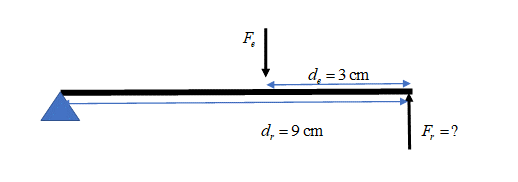
- Some tweezers (a 3rd class lever) are being used to remove a splinter. The length of the tweezers is [latex]\scriptsize \text{9 cm}[/latex].
.
The splinter will break if the force on it is greater than [latex]\scriptsize 10\text{ N}[/latex]. If the fingers are placed [latex]\scriptsize 3\text{ cm}[/latex] from the tip of the tweezers, what is the maximum, squeezing force that should be applied to remove the splinter? Draw a diagram to assist you with your answer. - Look at the lever below. The lever is pushed down to crush a can. The lengths of the input arm ([latex]\scriptsize {{d}_{e}}[/latex]) and the output arm ([latex]\scriptsize {{d}_{r}}[/latex]) are indicated.
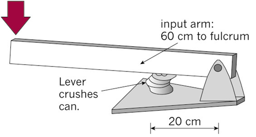
- With the can in the position shown, calculate the mechanical advantage this lever will give.
- How do you know that this lever will crush a can more easily than by hand?
- The designer decides to make it even easier to crush the can. She moves the can closer to the fulcrum. This reduces the output arm to [latex]\scriptsize 15\text{ cm}[/latex]. Recalculate the mechanical advantage of the lever.
- Look at the lifting system illustrated below. It uses a hydraulic cylinder for the input force. It is a system that could be used for lifting an engine out of a motorcar. The lifting lever at the top is a 3rd class lever, because the input is between the fulcrum and the output. A 3rd class lever always gives a distance advantage. It never gives a mechanical advantage.
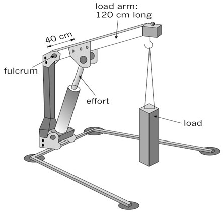
- How long is the input arm on this lever?
- How long is the output arm?
- Calculate the mechanical advantage that this lever gives.
- Explain what this MA value indicates about the output force ([latex]\scriptsize {{F}_{r}}[/latex]) compared to the input force ([latex]\scriptsize {{F}_{e}}[/latex]).
- A person wants to use this system to lift an engine out of a car. He needs the engine to be lifted by [latex]\scriptsize 90\text{ cm}[/latex]. How far will the hydraulic cylinder at the input need to move for the engine to be lifted [latex]\scriptsize 90\text{ cm}[/latex] at the output?
The full solutions are at the end of the unit.
Unit 2: Solutions
Exercise 2.1
- .
[latex]\scriptsize \begin{array}{l}{{F}_{e}}\text{ x }{{d}_{e}}\text{ }={{F}_{r}}\text{ x }{{d}_{r}}\\{{F}_{e}}\text{ x 1}\text{.5 = 60 x 2}\\\text{ }{{F}_{e}}\text{ = 80 kg}\end{array}[/latex] - .
[latex]\scriptsize \begin{array}{l}\text{ }{{F}_{e}}\text{ x }{{d}_{e}}={{F}_{r}}\text{ x }{{d}_{r}}\\3.5\text{ x 90 = 1 x }{{d}_{r}}\\\text{ }{{d}_{r}}\text{ = 315 cm}\end{array}[/latex] - .
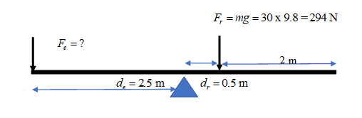
.
[latex]\scriptsize \begin{array}{l}\text{ }{{F}_{e}}\text{ x }{{d}_{e}}={{F}_{r}}\text{ x }{{d}_{r}}\\{{F}_{e}}\text{ x 2}\text{.5 = 294 x 0}\text{.5}\\\text{ }{{F}_{e}}\text{ = 58}\text{.8 N}\end{array}[/latex] - .
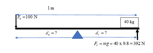
.
[latex]\scriptsize \begin{array}{l}\text{ }{{F}_{e}}\text{ x }{{d}_{e}}={{F}_{r}}\text{ x }{{d}_{r}}\\\text{ 100 x }{{d}_{e}}\text{ = 392 x }{{d}_{r}}\\\text{ but }{{d}_{e}}+{{d}_{r}}=1\text{ m, so }{{d}_{e}}=1-{{d}_{r}}\\\text{100 x (1}-{{d}_{r}}\text{) = 392 x }{{d}_{r}}\text{ }\\\text{ 100}-100{{d}_{r}}=392{{d}_{r}}\\\text{ }100=492{{d}_{r}}\\\text{ }{{d}_{r}}=0.203\text{ m}\end{array}[/latex]
.
The fulcrum must be placed [latex]\scriptsize 0.203\text{ m}[/latex] from the rock.
Exercise 2.2
- .
[latex]\scriptsize MA=\displaystyle \frac{{{{F}_{r}}}}{{{{F}_{e}}}}=\displaystyle \frac{{125}}{{25}}=4[/latex] - .
[latex]\scriptsize \begin{array}{l}MA=\displaystyle \frac{{{{F}_{r}}}}{{{{F}_{e}}}}\\\text{ }6\text{ }=\displaystyle \frac{{300}}{{{{F}_{e}}}}\\\text{ }{{F}_{e}}=50\text{ N}\end{array}[/latex] - .
[latex]\scriptsize \begin{array}{l}{{F}_{g}}=mg=10\text{ x 9}\text{.8=98 N}\\MA=\displaystyle \frac{{{{F}_{r}}}}{{{{F}_{e}}}}\\\text{ 4 }=\displaystyle \frac{{98}}{{{{F}_{{_{e}}}}}}\\\text{ }{{F}_{e}}=\displaystyle \frac{{98}}{4}\\\text{ }=24.5\text{ N}\end{array}[/latex] - .
[latex]\scriptsize \begin{array}{l}MA=\displaystyle \frac{{{{d}_{e}}}}{{{{d}_{r}}}}\\2.5\text{ }=\displaystyle \frac{6}{{{{d}_{r}}}}\\\text{ }{{d}_{r}}=2.4\text{ m}\end{array}[/latex]
Unit 2: Assessment
- .
- .
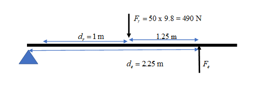
- .
[latex]\scriptsize MA=\displaystyle \frac{{{{d}_{e}}}}{{{{d}_{r}}}}=\displaystyle \frac{{2.25}}{1}=2.25[/latex] - .
[latex]\scriptsize \begin{array}{l}\text{ }{{F}_{e}}\text{ x }{{d}_{e}}={{F}_{r}}\text{ x }{{d}_{r}}\\{{F}_{e}}\text{ x 2}\text{.25 = 490 x 1}\\\text{ }{{F}_{e}}\text{ = 392 N}\end{array}[/latex]
- .
- .
.
[latex]\scriptsize \begin{array}{l}{{F}_{e}}\text{ x }{{d}_{e}}=30\text{ x 2 = 60}\\{{F}_{r}}\text{ x }{{d}_{r}}=22\text{ x 2}\text{.5 = 55}\\{{F}_{e}}\text{ x }{{d}_{e}}\ne {{F}_{r}}\text{ x }{{d}_{r}}\end{array}[/latex]
.
The seesaw will not be balanced. - .
.
[latex]\scriptsize \begin{array}{l}{{F}_{e}}\text{ x }{{d}_{e}}={{F}_{r}}\text{ x }{{d}_{r}}\\\text{ }{{F}_{e}}\text{ x 3 = 10 x 9}\\\text{ }{{F}_{e}}\text{ = 30 N}\end{array}[/latex] - .
- [latex]\scriptsize MA=\displaystyle \frac{{{{d}_{e}}}}{{{{d}_{r}}}}=\displaystyle \frac{{60}}{{20}}=3[/latex]
- MA indicates that the output force of the lever is [latex]\scriptsize 3[/latex] times that of the input force (force of the hand). Less force is required from the hand therefore it will be easier with the lever.
- [latex]\scriptsize MA=\displaystyle \frac{{{{d}_{e}}}}{{{{d}_{r}}}}=\displaystyle \frac{{60}}{{15}}=4[/latex]
- .
- [latex]\scriptsize 40\text{ cm}[/latex]
- [latex]\scriptsize 120\text{ cm}[/latex]
- [latex]\scriptsize MA=\displaystyle \frac{{{{d}_{e}}}}{{{{d}_{r}}}}=\displaystyle \frac{{40}}{{120}}=0.33[/latex]
- The output force is less than the input force.
- .
[latex]\scriptsize \begin{array}{l}MA=\displaystyle \frac{{{{d}_{e}}}}{{{{d}_{r}}}}\\0.33=\displaystyle \frac{{{{d}_{e}}}}{{90}}\\\text{ }{{d}_{e}}=30\text{ cm}\end{array}[/latex]
Media Attributions
- img01_Figure1 © L Kleynhans is licensed under a CC BY (Attribution) license
- img02_Example2.1 © L Kleynhans is licensed under a CC BY (Attribution) license
- QR_Code_PSL2SO24U2_1
- img03_Activity2.1 © PHeT is licensed under a CC BY (Attribution) license
- img04_Figure2 © L Kleynhans is licensed under a CC BY (Attribution) license
- img05_Figure3 © L Kleynhans is licensed under a CC BY (Attribution) license
- img06_Figure4 © L Kleynhans is licensed under a CC BY (Attribution) license
- img07_AssessmentQ3 © unknown is licensed under a CC0 (Creative Commons Zero) license
- img08_AssessmentQ4 © L Kleynhans is licensed under a CC BY (Attribution) license
- img09_AssessmentQ5 © DHET is licensed under a CC BY (Attribution) license
- img10_Ex2.1Q3answer © DHET is licensed under a CC BY (Attribution) license
- img11_Ex2.1Q4answer © DHET is licensed under a CC BY (Attribution) license
- img12_AssessmentQ1a)answer © DHET is licensed under a CC BY (Attribution) license
- img13_AssessmentQ2answer © DHET is licensed under a CC BY (Attribution) license
- img14_AssessmentQ3answer © DHET is licensed under a CC BY (Attribution) license
the amount of effort saved when using a machine
