Waves, sound and light: Identify, describe and apply principles of geometrical optics in everyday contexts
Unit 1: Wave properties of light: Reflection and refraction
Linda Pretorius
Unit 1 outcomes
By the end of this unit you will be able to:
- Identify light as a transverse wave.
- Identify and describe the wave properties of light with reference to:
- refraction
- reflection
- Draw and interpret diagrams of refraction, showing:
- the angle of the light ray in two media
- the normal.
- Draw and interpret diagrams showing total internal reflection.
Introduction
Mirrors, reading glasses, telescopes, methods of communication, spotlights and car headlights all manipulate the way light reflects off surfaces or refracts in different media. and are phenomena that occur because of the wave properties of light. If light did not behave the way it does, we would not be able to use a mirror to see how we look before going out, use glasses to correct eye problems, look at objects far away or communicate over long distances.
In this unit[1] you will build on your knowledge of the properties of transverse waves to understand how light behaves, and draw simple ray diagrams to support your understanding. This will help you to understand how we use the behaviour of light in practical applications.
Light is a wave
You know from Subject outcome 3.1 on waves that energy travels in waves. Light is a form of energy, and it follows that light also travels in waves. Although we generally cannot see these waves, it is useful to understand light as a transverse wave to help us understand how it behaves and how to manipulate it to create specific effects.
In physics we use the idea of a light ray to show the direction in which the wave propagates, in other words, the direction in which light travels. Light rays are generally shown as straight arrows.
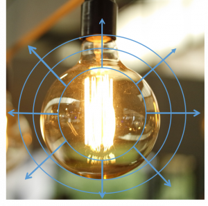
The light bulb in Figure 1 is a source of light. The are shown by the concentric circles coming from the bulb. We represent the direction in which the wavefronts are moving by drawing light rays (the arrows) perpendicular to the wavefronts. You can think of a light ray as the path of a point on the crest of a wave.
The study of how light interacts with materials is called . When dealing with light rays, we are usually interested in the shape of a surface and the angles at which light rays hit it. From these angles, we can determine, for example, the distance between an object and its reflection. We call these methods .
In geometrical optics, we represent light rays as straight arrows to show how light propagates. Light rays are not an exact description of the light; rather they show the direction in which the light wavefronts are travelling.
We can only see an object when light from the object enters our eyes. The object must either be a source of light (e.g. a light bulb) or it must reflect light from a source (e.g. the moon which reflects light from the sun), and the light must enter our eyes.
When light interacts with an object or a medium, such as glass or water, it displays certain characteristic behaviours: it can be reflected, refracted, absorbed or transmitted. Let us look at reflection in more detail.
Reflection
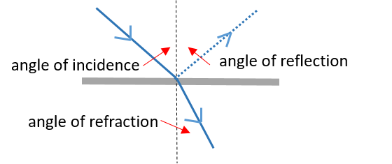
Reflection occurs when a wave bounces off a surface, such as when light hits a shiny material such as polished metal or a mirror. Figure 2 shows a summary of what happens when light is reflected off a smooth reflective surface.
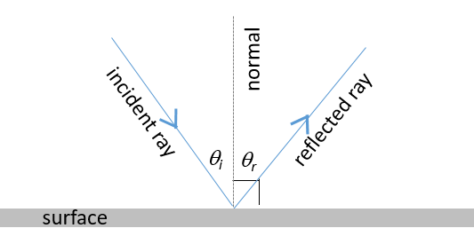
- The light ray that falls on the surface is called the incident ray. The light ray moving away from the surface is the reflected ray.
- The angle of the light ray in relation to the reflecting surface determines the nature of the reflection. These angles are measured with respect to the normal of the surface. The normal is an imaginary line perpendicular to the surface.
- The angle of incidence, [latex]\scriptsize {{\theta }_{\text{i}}}[/latex], is measured between the incident ray and the normal.
- The angle of reflection, [latex]\scriptsize {{\theta }_{\text{r}}}[/latex], is measured between the reflected ray and the normal.
- When light is reflected, the angle of incidence is equal to the angle of reflection.
- The incident ray, the reflected ray and the normal all lie in the same plane.
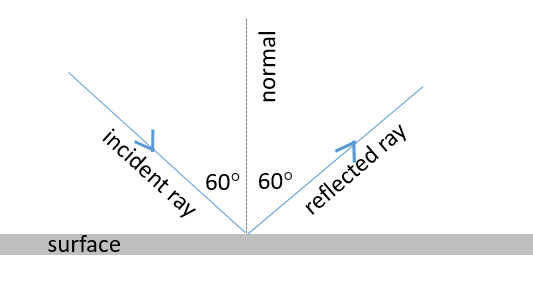
The law of reflection states that the angle of incidence is equal to the angle of reflection: [latex]\scriptsize {{\theta }_{\text{i}}}={{\theta }_{\text{r}}}[/latex] and the incident ray, the reflected ray and the normal all lie in the same plane.
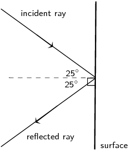
From the law of reflection, it therefore follows that if a light ray strikes a surface at [latex]\scriptsize 60{}^\circ[/latex] to the normal, the angle that the reflected ray makes with the normal will also be [latex]\scriptsize 60{}^\circ[/latex], as shown in the following ray diagram.
Exercise 1.1
- A ray of light strikes a surface at [latex]\scriptsize 15{}^\circ[/latex] to the normal.
- Draw a simple ray diagram showing the incident ray, reflected ray and surface normal.
- Fill in the angles of incidence and reflection on the diagram.
- A ray of light strikes a surface at [latex]\scriptsize 25{}^\circ[/latex]. Draw a ray diagram showing the incident ray, reflected ray and surface normal. Calculate the angles of incidence and reflection and fill them in on your diagram.
The full solutions are at the end of the unit.
Refraction
In the previous section we studied light reflecting off various surfaces. What happens when light passes from one medium into another, in other words it crosses a boundary between two mediums?
As you learnt in SO 3.1 Unit 3, the speed of a wave depends on the properties of the medium it travels in. When a wave crosses into a denser medium, it slows down. Conversely, when it crosses into a less dense medium, it speeds up. The same applies to light, because light is also a wave. In the case of light, we refer to the of the medium. You will learn more about this later in this unit.
One of the most exciting discoveries in physics during the last century, and the cornerstone of Einstein’s theory of relativity, is that light travels at a constant speed in a given medium. Light also has a maximum speed at which it can propagate, and nothing can move faster than the speed of light.
Light travels at its maximum speed through a . We use the symbol c to represent the speed of light in a vacuum and approximate it as [latex]\scriptsize c=3\times {{10}^{8}}\ \text{m}\cdot {{\text{s}}^{{-1}}}[/latex]. The speed of light in air is very close to that in a vacuum, and therefore we can confidently use this value for calculations that involve light travelling through air.
The speed of light is constant in a given medium and has a maximum speed in a vacuum:
[latex]\scriptsize c=3\times {{10}^{8}}\ \text{m}\cdot {{\text{s}}^{{-1}}}[/latex]
When light moves from one medium into another (for example, from air to glass), its speed changes. This change in speed is usually associated with a change in the direction of the light ray. That is, if the light ray hits the boundary of the new medium (for example, the edge of a glass block) at any angle that is not perpendicular to or parallel with the boundary, the light ray will change its direction through the next medium. The light ray will therefore appear to ‘bend’. This is called of light. It is important to note that while the speed of the light changes when it passes into the new medium, the frequency of the light remains the same.
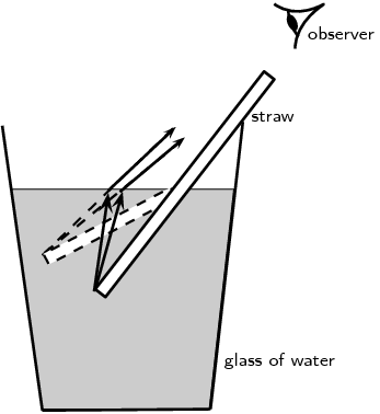
Refraction is nicely demonstrated when you look from above but at an angle at a drinking straw in a glass of water. The straw appears bent in the liquid. This is because the light rays reflecting off the straw change direction when they hit the surface between the liquid and the air. Your eyes trace the light rays backwards as straight lines to the point they would have come from if they had not changed direction and as a result you see the tip of the straw as being shallower in the liquid than it really is, as shown in Figure 4.
Refractive index and optical density
The speed of light, and therefore the degree of bending of the light, depends on the refractive index of the material through which the light passes. The refractive index (symbol n) is the ratio of the speed of light in a vacuum to its speed in the material, and gives an indication of how difficult it is for light to get through the material.
The refractive index of a material is given as [latex]\scriptsize n=\displaystyle \frac{c}{v}[/latex]
where:
n = refractive index (no unit)
c = speed of light in a vacuum ([latex]\scriptsize 3\times {{10}^{8}}\ \text{m}\cdot {{\text{s}}^{{-1}}}[/latex])
v = speed of light in a given medium (m.s–1)
From the definition of the refractive index, [latex]\scriptsize n=\displaystyle \frac{c}{v}[/latex], we can see that the speed of light in a given medium (v) and the refractive index (n) are inversely proportional. Because the speed of light in a vacuum (c) is constant, it follows that if the refractive index increases, the speed of light in the material must decrease. Therefore light travels slower through materials of high refractive index.
Table 1 shows refractive indices for various materials. Light travels slower in any material than it does in a vacuum, so all values for n are greater than 1.
Optical density is a measure of the refracting power of a medium. In other words, the higher the optical density, the more the light will be refracted or slowed down as it moves through the medium. Optical density is related to refractive index in that materials with a high refractive index will also have a high optical density. Light will travel slower through a medium with a high refractive index and high optical density, and faster through a medium that has a low refractive index and a low optical density.
Example 1.1
Calculate the speed of light through glycerine.
Solution
From Table 1, we know that the refractive index (n) of glycerine is [latex]\scriptsize 1.4729[/latex]. We also know that the speed of light in a vacuum is a constant: [latex]\scriptsize c=3\times {{10}^{8}}\ \text{m}\cdot {{\text{s}}^{{-1}}}[/latex].
To calculate the speed of light in glycerine, we rearrange the equation [latex]\scriptsize n=\displaystyle \frac{c}{v}[/latex] to make speed the subject:
[latex]\scriptsize \begin{align*}v & =\displaystyle \frac{c}{n}\\ & =\displaystyle \frac{{3\times {{{10}}^{8}}\text{ m}\cdot {{\text{s}}^{{-1}}}}}{{1.4729}}\\ & =2.04\times {{10}^{8}}\text{ m}\cdot {{\text{s}}^{{-1}}}\end{align*}[/latex]
Activity 1.1: Explore how light bends
Time required: 10 minutes
What you need:
- an internet connection
- a computer or tablet
- a calculator
- a pen and a notebook
What to do:
- Access the simulation called Bending light.
Choose the ‘Intro’ option. - .
- Set both mediums to ‘Air’ using the control panels on the right of the screen. Notice that the horizontal line represents the boundary between the two mediums. The dashed vertical line represents the normal to the surface.
- Switch on the torch. What do you notice?
Note
You can also move the torch around to change the angle of the beam. - Set both mediums to water or glass now. What do you notice?
- Now set the bottom medium to water.
- Notice the index of refraction.
- How did the direction of the light beam change?
- What does the feint line above the boundary represent?
- Now set the incident medium to a higher index of refraction (e.g. water) and let the refracting medium have a lower index (e.g. air). Notice the appearance of the reflected ray.
- How does the direction of the beam change?
- What happens when you increase the index of refraction of the refracting medium gradually?
- What change do you notice in the reflected ray?
- Make the two mediums the same again (e.g. air, [latex]\scriptsize n=1.00[/latex]). Increase the index of refraction of the incident medium (top) gradually using the slider.
- How does the reflected ray change?
- Up to what point does the angle of refraction keep on increasing? What happens after that point?
What did you find?
- The light beam travels straight when the mediums are the same; no refraction occurs (step 2). It does not matter whether the refractive index is high or low; as long as they are the same for both mediums, no refraction occurs.
- The index of refraction of the bottom medium is now [latex]\scriptsize 1.33[/latex] (step 3), which is higher than the index of refraction of air ([latex]\scriptsize n=1.00[/latex]). The light ray now bends towards the normal, and the angle of refraction is smaller than the angle of incidence. The higher index of refraction tells us that the optical density has increased. The wave therefore slows down in the refracting medium, which causes it to bend towards the normal.
We also notice a feint ray above the boundary, which shows that some reflection also occurs. Notice that the angle of incidence is equal to the angle of reflection: [latex]\scriptsize {{\theta }_{\text{i}}}={{\theta }_{\text{r}}}[/latex].
Take note!
Do not confuse the angle of reflection and the angle of refraction.
- When the refracting medium (bottom) has a lower optical density compared with the incident (top) medium (step 4), the ray bends away from the normal, and the angle of refraction becomes bigger than the angle of incidence. The wave therefore moves faster through the refracting medium and so bends away from the normal.
The angle of refraction decreases as the index of refraction is increased. This is because the optical density increases, and the wave moves slower. The ray therefore bends towards the normal again. The more the ray is refracted towards the normal, the feinter the reflected ray becomes. This tells us that there is less reflection off the surface of the boundary. - When the index of refraction of the incident medium is higher than that of the refracting medium (step 5), the refracted ray will bend way from the normal. At some critical index, the angle of refraction exceeds [latex]\scriptsize 90{}^\circ[/latex] and all the light it reflected off the boundary surface. No refraction occurs beyond this value. You will learn more about this phenomenon later in the section.
Ray diagrams of refraction
It is useful to draw ray diagrams to understand how the geometrical optics concepts work. In ray diagrams, we have to show the:
- incident ray
- refracted ray
- angle of incidence
- angle of refraction
- boundary between the mediums
- normal.
It is useful to label the mediums or at least show the indices of refraction.
Also remember the following concepts:
- normal – the line that is perpendicular to the plane of the surface
- angle of incidence – the angle between the normal and the incident light ray
- angle of refraction – the angle between the normal and the refracted light ray.
Let’s look at an example.
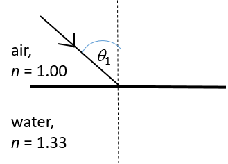
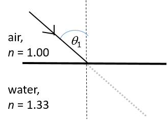
Example 1.2
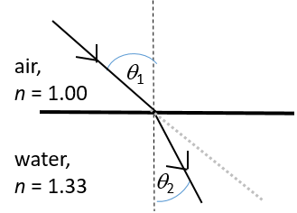
Draw a ray diagram to show the refraction of a light ray moving from air ([latex]\scriptsize n=1.00[/latex]) into water ([latex]\scriptsize n=1.33[/latex]).
Solution
 |
|
 |
|
 |
|
 |
|
 |
|
Activity 1.2: Understand refraction of light
Time required: 15 minutes
What you need:
- a computer, tablet or phone connected to the internet
- a pen and a notebook
What to do:
- Watch the video called Refraction of light (Duration 09.40).
- Note the angle of incidence.
- Describe how the direction of the ray changes as it moves through the glass block.
What did you find?
- The angle of incidence is [latex]\scriptsize 30{}^\circ[/latex]. The pins show the path of light in air. Connecting the point of entrance into and point of exit out of the glass shows the path of the ray inside the glass block. We can see that the ray was refracted twice: once when it moved from the air into the glass block, and again when it moved out of the glass block back into the air.
- When the light entered the glass block, it bent towards the normal: the angle of refraction is smaller than the angle of incidence.
- A new angle of incidence is defined for the ray that strikes the boundary between glass and air at the exit point. When the light moved out of the glass block, back into air, this ray bent away from the normal. The angle of refraction is bigger than the newly defined angle of incidence.
Total internal reflection
Recall from the last part of Activity 1.1 that for a specific combination of optical mediums, no refraction occurred when the light ray moved from the optically denser medium into the one that was less dense. Instead all the light was reflected. This phenomenon is called . In other words, all the light is reflected back into the incident medium once it hits the boundary between the two mediums.
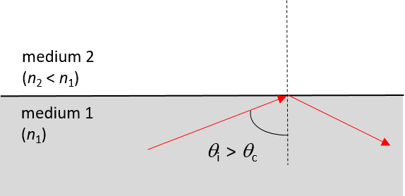
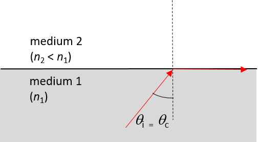
Total internal reflection is a special case of refraction (see Figure 5). For each pair of optical mediums there is a specific angle – called the – at which an incident ray will be refracted by [latex]\scriptsize 90{}^\circ[/latex] when it reaches the boundary between the two mediums. If the incident ray strikes the boundary between the two mediums at any angle greater than the critical angle, the light ray will be reflected back into the incident medium, and not be refracted at all.
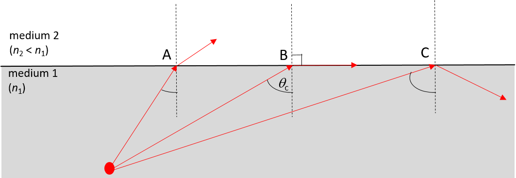
(B) When the angle of incidence is equal to the critical angle ([latex]\scriptsize \theta_c[/latex]), the light ray is refracted by [latex]\scriptsize 90\text{}^\circ[/latex].
(C) When the angle of incidence is greater than the critical angle, no refraction occurs and the light ray is reflected back into the incident medium.
Do Activity 1.3 to explore critical angles and total internal reflection.
Activity 1.3: Explore critical angles and total internal reflection
Time required: 5 minutes
What you need:
- an internet connection
- a computer or tablet
- a calculator
- a pen and a notebook
What to do:
- Access the simulation called Bending light.

Choose the ‘Intro’ option. - Set the incident medium (top) to ‘Water’ and the other medium (bottom) to ‘Air’ using the control panels on the right of the screen.
- Move the torch towards the normal to create a fairly small angle of incidence. Switch on the torch. What do you notice?
- Move the torch away from the normal to gradually increase the angle of incidence. What do you notice?
- Increase the angle of incidence some more. What do you notice?
What did you find?
- When the angle of incidence is small (step 3), the light ray is refracted away from the normal at the boundary between the two mediums.
- As the angle of incidence increases (step 4), the angle of refraction also increases. Beyond a specific angle, the light ray is not refracted at all, but rather reflected back into the incident medium.
- The light ray remains internally reflected even as the angle of incidence increases more (step 5). The angle of incidence is always equal to the angle of reflection.
The two conditions for total internal reflection are that:
- light must be travelling from an optically denser medium (higher refractive index) to an optically less dense medium (lower refractive index)
- the angle of incidence must be greater than the critical angle for the pair of mediums.
Total internal reflection is useful in optical instruments such as binoculars and telescopes because light is reflected with very little loss. This helps to create sharp images.
Total internal reflection is also used in fibre-optic technology. An optical fibre is a very thin, transparent fibre, usually made of glass or plastic, for transmitting light. The basic functional structure of an optical fibre consists of an outer protective cladding and an inner core through which light pulses travel. The overall diameter of the fibre is about [latex]\scriptsize 125\ \text{ }\!\!\mu\!\!\text{ m}[/latex] and that of the core is only about [latex]\scriptsize 50\ \text{ }\!\!\mu\!\!\text{ m}[/latex].
The difference in refractive index of the cladding and the core allows total internal reflection to occur in the same way as happens at an air–water surface. If light is incident on a cable end with an angle of incidence greater than the critical angle, then the light will remain trapped inside the glass strand. In this way, light travels very quickly down the length of the cable.
Calculating the critical angle
Remember that each pair of optical mediums has a specific critical angle. For example, the critical angle for light moving from glass to air is [latex]\scriptsize 42{}^\circ[/latex], and that of water to air is [latex]\scriptsize 48.8{}^\circ[/latex].
Instead of always having to measure the critical angles of different materials, it is possible to calculate the critical angle at the surface between two media using Snell’s Law.
Snell’s Law states:
[latex]\scriptsize {{n}_{1}}\sin {{\theta }_{1}}={{n}_{2}}\sin {{\theta }_{2}}[/latex]
where [latex]\scriptsize {{n}_{1}}[/latex] is the refractive index of material 1, [latex]\scriptsize {{n}_{2}}[/latex] is the refractive index of material 2, [latex]\scriptsize {{\theta }_{1}}[/latex] is the angle of incidence and [latex]\scriptsize {{\theta }_{2}}[/latex] is the angle of refraction.
For total internal reflection, we know that the angle of incidence is the critical angle. So: [latex]\scriptsize {{\theta }_{2}}={{\theta }_{\text{c}}}[/latex].
However, we also know that the angle of refraction at the critical angle is [latex]\scriptsize 90{}^\circ[/latex]. So we have:
[latex]\scriptsize {{\theta }_{2}}=90{}^\circ[/latex]
We can then write Snell’s Law as:
[latex]\scriptsize {{n}_{1}}\sin {{\theta }_{\text{c}}}={{n}_{2}}\sin 90{}^\circ[/latex]
Solving for [latex]\scriptsize {{\theta }_{\text{c}}}[/latex] gives:
[latex]\scriptsize \begin{align*}{{n}_{1}}\sin {{\theta }_{\text{c}}} & ={{n}_{2}}\sin 90{}^\circ \\\sin {{\theta }_{\text{c}}} & =\displaystyle \frac{{{{n}_{2}}}}{{{{n}_{1}}}}(1)\\\therefore {{\theta }_{\text{c}}} & ={{\sin }^{{-1}}}(\displaystyle \frac{{{{n}_{2}}}}{{{{n}_{1}}}})\end{align*}[/latex]
Exercise 1.2
- Describe total internal reflection by using a diagram and referring to the conditions that must be satisfied for total internal reflection to occur.
- Define what is meant by the critical angle when referring to total internal reflection. Include a ray diagram to explain the concept.
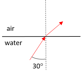
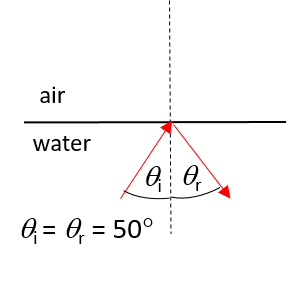
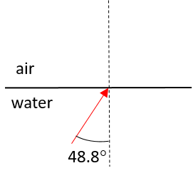
- Complete the following ray diagrams to show the path of light in each situation.
- .

- .

- .

- .
- .
The full solutions are at the end of the unit.
Summary
In this unit you have learnt the following:
- Light energy travels as a wave.
- The study of how light interacts with materials is called optics.
- In geometrical optics, we represent light rays as straight arrows to show how light propagates.
- Reflection occurs when a wave bounces off a surface, such as when light hits a shiny material like polished metal or a mirror.
- The law of reflection states that the angle of incidence is equal to the angle of reflection: [latex]\scriptsize {{\theta }_{\text{i}}}={{\theta }_{\text{r}}}[/latex]. The incident ray, the reflected ray and the normal all lie in the same plane.
- When light moves from one medium into another at an angle, its speed changes and consequently it changes direction. The light ray will therefore appear to ‘bend’. This is called refraction of light.
- The speed of light, and therefore the degree of refraction, depends on the refractive index of the material through which the light passes.
- The refractive index of a material is given as [latex]\scriptsize n=\displaystyle \frac{c}{v}[/latex].
- Light travels at its maximum speed through a vacuum: [latex]\scriptsize c=3\times {{10}^{8}}\ \text{m.}{\text{s}}^{{-1}}[/latex].
- Optical density is a measure of the refracting power of a medium. The higher the optical density, the more the light will be refracted (slowed down) as it moves through the medium.
- Ray diagrams are useful to understand refraction. A ray diagram shows the incident and refracted rays, the angles of incidence and refraction, the boundary between the mediums, and the normal ray.
- When light travels from an optically denser medium to one that is less dense, the ray will be refracted by [latex]\scriptsize 90{}^\circ[/latex] if the angle of incidence is equal to the critical angle for the combination of mediums.
- Total internal reflection occurs for any angle of incidence greater than the critical angle when light travels from an optically denser medium to one that is less dense.
- Total internal reflection is useful in applications such as fibre optics, telescopes and binoculars.
Unit 1: Assessment
Suggested time to complete: 35 minutes
Questions were taken from exercises 5-1, 5-2, 5-3 and the End-of-Chapter exercise in the Siyavula Gr 11 Physical Science Learner’s Book on pp. 199–200, 205, 210–211, and 230–231, released under a CC-BY licence.
- Give one word for each of the following descriptions:
- The perpendicular line that is drawn at right angles to a reflecting surface at the point of incidence.
- The bending of light as it travels from one medium to another.
- The bouncing of light off a surface.
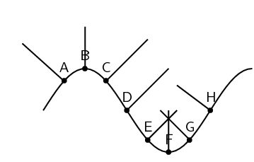
- The diagram below shows a curved surface. Draw normals to the surface at the marked points.
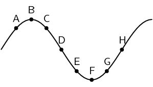
- Which of the labels, A–E, in the diagram, correspond to the following:
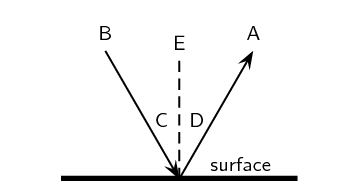
- normal
- angle of incidence
- angle of reflection
- incident ray
- reflected ray
- Use the values given in Table 1, and the definition of refractive index, to calculate the speed of light in water (ice).
- Calculate the refractive index of an unknown material through which the speed of light is [latex]\scriptsize 1.974\times {{10}^{8}}\text{ m}\cdot {{\text{s}}^{{-1}}}[/latex]. Round off your answer to two decimal places. Using Table 1, identify what the unknown material is.
- A ray of light leaves a surface at [latex]\scriptsize 65{}^\circ[/latex] to the surface. Draw a ray diagram showing the incident ray, the reflected ray and the normal. Calculate the angles of incidence and reflection and fill them in on the diagram.
- Light travels from glass ([latex]\scriptsize n=1.5[/latex]) to acetone ([latex]\scriptsize n=1.36[/latex]).
- Describe the path of light as it moves into the acetone.
- What happens to the speed of the light as it moves from the glass to the acetone?
- What happens to the wavelength of the light as it moves into the acetone?
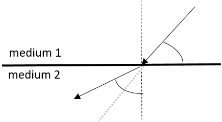
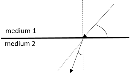
- In the diagram below, a ray of light strikes the interface between two mediums.

Draw what the refracted ray would look like if:- medium 1 had a higher refractive index than medium 2.
- medium 1 had a lower refractive index than medium 2.
- Will light travelling from diamond to silicon undergo total internal reflection? Give a reason for your answer.
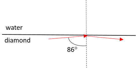
- Light travelling from diamond to water strikes the interface with an angle of incidence of [latex]\scriptsize 86{}^\circ[/latex]. Determine whether the light will be refracted or totally internally reflected. Draw a diagram to support your answer.
The full solutions are at the end of the unit.
Unit 1: Solutions
Exercise 1.1
- .
- and b.

- and b.
- If the ray strikes the surface at [latex]\scriptsize 25{}^\circ[/latex], it means the ray makes an angle of [latex]\scriptsize 90{}^\circ -25{}^\circ =65{}^\circ[/latex] with the normal, which represents the angle of incidence.

Exercise 1.2
- Total internal reflection occurs when light travelling from an optically denser medium to one that is less dense strikes the boundary between the mediums at an angle greater than the critical angle.
- The critical angle is the angle of incidence that will result in a light ray being refracted by [latex]\scriptsize 90{}^\circ[/latex] when light travels from an optically denser medium to one that is less dense.
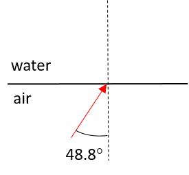
- First determine the critical angle for the air–water combination. If the light ray moves from water (medium 1) to air (medium 2), as in diagrams (a)–(c), [latex]\scriptsize {{n}_{1}}=1.33[/latex] and [latex]\scriptsize {{n}_{2}}=1.00[/latex].
.
From Snell’s law:
[latex]\scriptsize \begin{align*}{{n}_{1}}\sin {{\theta }_{\text{c}}} & ={{n}_{2}}\sin 90{}^\circ \\\sin {{\theta }_{\text{c}}} & =\displaystyle \frac{{1.00}}{{1.33}}(1)\\\therefore {{\theta }_{\text{c}}} & ={{\sin }^{{-1}}}(0.7518)\\ & =48.8{}^\circ \end{align*}[/latex]- [latex]\scriptsize {{\theta }_{\text{i}}}=30{}^\circ[/latex], which is smaller than the critical angle ([latex]\scriptsize 48.8{}^\circ[/latex]). The light ray will therefore be refracted away from the normal as it moves into the air.
- [latex]\scriptsize {{\theta }_{\text{i}}}=50{}^\circ[/latex], which is greater than the critical angle ([latex]\scriptsize 48.8{}^\circ[/latex]). The light ray will therefore be totally internally reflected. The angle of reflection will be equal to the angle of incidence.
- The angle of incidence is equal to the critical angle: [latex]\scriptsize 48.8{}^\circ[/latex]. The light ray will therefore be refracted by [latex]\scriptsize 90{}^\circ[/latex].
- The light ray now moves from air ([latex]\scriptsize n=1.00[/latex]) to water ([latex]\scriptsize n=1.33[/latex]). Air is optically less dense than water, so we know that the light ray will be refracted towards the normal; internal reflection is not possible.
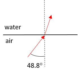
- [latex]\scriptsize {{\theta }_{\text{i}}}=30{}^\circ[/latex], which is smaller than the critical angle ([latex]\scriptsize 48.8{}^\circ[/latex]). The light ray will therefore be refracted away from the normal as it moves into the air.
Unit 1: Assessment
- .
- normal
- refraction
- reflection
- .
- .
- E
- C
- D
- B
- A
- The refractive index of ice is [latex]\scriptsize 1.31[/latex]. To calculate the speed of light in ice:
[latex]\scriptsize \begin{align*}n=\displaystyle \frac{c}{v}\\\therefore v & =\displaystyle \frac{c}{n}\\ & =\displaystyle \frac{{3.8\times {{{10}}^{8}}\ \text{m}\cdot {{\text{s}}^{{-1}}}}}{{1.31}}\\ & =2.29\times {{10}^{8}}\ \text{m}\cdot {{\text{s}}^{{-1}}}\end{align*}[/latex] - .
[latex]\scriptsize \begin{align*}n & =\displaystyle \frac{c}{v}\\ & =\displaystyle \frac{{3.8\times {{{10}}^{8}}\ \text{m}\cdot {{\text{s}}^{{-1}}}}}{{1.974\times {{{10}}^{8}}\ \text{m}\cdot {{\text{s}}^{{-1}}}}}\\ & =1.52\end{align*}[/latex]
.
According to the values in Table 1, the material is a form of glass. - The angle between the reflected ray and the surface is [latex]\scriptsize 65{}^\circ[/latex]. This means the angle between the reflected ray and the normal (the angle of reflection) must be [latex]\scriptsize 90{}^\circ -65{}^\circ =25{}^\circ[/latex]. The law of reflection states that the angle of reflection is equal to the angle of incidence. Therefore, the angle of incidence is [latex]\scriptsize 25{}^\circ[/latex].
- .
- The ray bends away from the normal.
- The speed increases.
- The wavelength increases because the frequency remains constant.
- .
- .
- .
- .
- Diamond ([latex]\scriptsize n=2.42[/latex]) is optically less dense than silicon [latex]\scriptsize n=4.01[/latex] and so total internal reflection cannot occur.
- The light ray moves from an optically denser medium, diamond [latex]\scriptsize \text{(}{{n}_{1}}=2.42 \text{)}[/latex] to an optically less dense medium, water [latex]\scriptsize \text{(} {{n}_{2}}=1.33 \text{)}[/latex]. Total internal reflection is therefore possible if the critical angle is exceeded.
.
From Snell’s law:
[latex]\scriptsize \begin{align*}{{n}_{1}}\sin {{\theta }_{\text{c}}} & ={{n}_{2}}\sin 90{}^\circ \\\sin {{\theta }_{\text{c}}} & =\displaystyle \frac{{{{n}_{2}}}}{{{{n}_{1}}}}(1)\\\sin {{\theta }_{\text{c}}} & =\displaystyle \frac{{1.33}}{{2.42}}(1)\\\therefore {{\theta }_{\text{c}}} & ={{\sin }^{{-1}}}(0.5496)\\ & =33.34{}^\circ \end{align*}[/latex]
.
[latex]\scriptsize {{\theta }_{\text{i}}}=86{}^\circ[/latex], which exceeds the critical angle, and therefore the light will be internally reflected. Note that the angle of reflection will be equal to the angle of incidence, in accordance with the law of reflection.
Media Attributions
- Img01_Light rays © Pexels is licensed under a CC0 (Creative Commons Zero) license
- Img02_Reflection © DHET is licensed under a CC BY (Attribution) license
- Img03_Law of reflection © DHET is licensed under a CC BY (Attribution) license
- Img06_Refraction © Siyavula is licensed under a CC BY (Attribution) license
- QR_Code_PSL2SO32U1_1
- Img07_Reflection vs refraction © DHET is licensed under a CC BY (Attribution) license
- Img08a_Ray diagram 1 © DHET is licensed under a CC BY (Attribution) license
- Img08b_Ray diagram 2 © DHET is licensed under a CC BY (Attribution) license
- Img08c_Ray diagram 3 © DHET is licensed under a CC BY (Attribution) license
- Img08d_Ray diagram 4 © DHET is licensed under a CC BY (Attribution) license
- Img08e_Ray diagram 5 © DHET is licensed under a CC BY (Attribution) license
- QR_Code_PSL2SO32U1_2
- Img016_Total internal reflection © DHET is licensed under a CC BY (Attribution) license
- QR_Code_PSL2SO32U1_3
- Img017_Exercise1.2 Q3a © DHET is licensed under a CC BY (Attribution) license
- Img018_Exercise1.2 Q3b © DHET is licensed under a CC BY (Attribution) license
- Img019_Exercise1.2 Q3c © DHET is licensed under a CC BY (Attribution) license
- Img020_Exercise1.2 Q3d © DHET is licensed under a CC BY (Attribution) license
- Img04_AssmntQ2 © Siyavula is licensed under a CC BY (Attribution) license
- Img05_AssmntQ3 © Siyavula is licensed under a CC BY (Attribution) license
- Img09_AssmntQ8 © DHET is licensed under a CC BY (Attribution) license
- Img014_Exercise1.1_Q1_answer © DHET is licensed under a CC BY (Attribution) license
- Img015_Exercise1.1_Q2_answer © DHET is licensed under a CC BY (Attribution) license
- Img021_Exercise 1.2_Q1 answer © DHET is licensed under a CC BY (Attribution) license
- Img022_Exercise 1.2_Q2 answer © DHET is licensed under a CC BY (Attribution) license
- Img023_Exercise 1.2_Q3a answer © DHET is licensed under a CC BY (Attribution) license
- Img024_Exercise 1.2_Q3b answer © DHET is licensed under a CC BY (Attribution) license
- Img025_Exercise 1.2_Q3c answer © DHET is licensed under a CC BY (Attribution) license
- Img026_Exercise 1.2_Q3d answer © DHET is licensed under a CC BY (Attribution) license
- Img010_AssmntQ2_answer © DHET is licensed under a CC BY (Attribution) license
- Img011_AssmntQ6_answer © DHET is licensed under a CC BY (Attribution) license
- Img012_AssmntQ8_answerA © DHET is licensed under a CC BY (Attribution) license
- Img013_AssmntQ8_answerB © DHET is licensed under a CC BY (Attribution) license
- Img027_Assmnt_Q10 answer © DHET is licensed under a CC BY (Attribution) license
- Parts of the text in this unit were sourced or adapted from Siyavula Physical Science Gr 11 Learner’s Book, p. 194–199, released under a CC-BY licence. ↵
light (or sound) waves being bounced back off a surface
the change in the direction of a light wave as it moves from one optical medium to another
the crest of a transverse wave moving outwards from the source
the study of the behaviour of light
the study of light rays, and specifically the effects of lenses and mirrors on light rays
the degree to which a refractive medium slows down light rays as it travels through that medium
a space that contains no matter
the phenomenon that results in light being trapped inside an optically denser medium instead of being refracted when it strikes the boundary between the denser and less dense medium
the angle of incidence that will result in a light ray being refracted by 90 degrees when it moves from an optically denser medium to one that is less dense
