Mechanics: Identify and apply principles of force
Unit 2: Force diagrams
Linda Pretorius
Unit outcomes
By the end of this unit you will be able to:
- Identify the system of interest on which forces act.
- Draw diagrams to show interacting force pairs acting on a system.
- Interpret force diagrams to predict the net effect of forces acting on a system.
What you should know
Before you start this unit, make sure you can:
- Distinguish between a vector and a scalar. Subject Outcome 2.1, Unit 3.
- Define a force. Subject Outcome 2.2, Unit 1.
- Identify different types of forces. Subject Outcome 2.2, Unit 1.
Introduction
Almost everything that happens in the world around us, and much of what we study in physics, is the result of forces. In the previous unit you learnt what a force is and how to identify different types of forces. This knowledge will help you to draw force diagrams. help us to visualise forces at work, and predict or understand the observed effect of forces.
What is a force diagram?
You already know from Unit 1 that we can see only the effects of forces on an object, not the forces themselves. A force diagram is a useful tool to help us visualise forces acting on an object and gives us information about the object’s motion. We often use force diagrams when solving calculations involving the forces acting on an object.
Here is an example. Imagine you want to visualise the forces acting on a Formula 1 race car as it accelerates towards the finish line.

Instead of drawing the actual car and trying to show in picture form that it is accelerating, we simply draw:
- a box to represent the car
- arrows to show the forces affecting its movement.
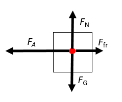
The force diagram shows us that the forces acting on the object in the vertical direction are balanced, these are the gravitational force FG and the normal force FN, because they are drawn at equal lengths. The forces in the horizontal direction, namely the applied force FA and the opposing frictional force Ffric, are unbalanced; therefore the arrow representing FA is longer than that of Ffric.
Notice the following important aspects of a force diagram:
- The object is drawn as a simple shape, usually a box or a big dot.
- Arrows are drawn from the centre of the object.
- Arrows represent the external forces acting on the object.
- The arrows are labelled to show the types of force, the size of the forces, or a combination of the information.
- Each arrow points in the direction of the force it represents.
- The length of an arrow shows the relative strength of the force.
Note
A force diagram is often also called a free-body diagram.
Working with force diagrams
Drawing and interpreting force diagrams starts to become easy when you remember that the diagram represents the external forces acting on an object and you know how to define the object.
We often refer to the object as a ‘’, especially when a collection of items act as if they are one object, such as a cart full of boxes being pushed by a person, or a car with a driver and a passenger inside the cabin and the engine in front. A force diagram therefore does not show:
- any internal forces acting within the system; for example, the forces exerted by a driver on the seat or steering wheel
- the forces acting on other objects in the surroundings; for example, forces on other cars surrounding the one we are interested in
- the forces exerted by the system itself; for example, the forces the car exerts on the road or its surroundings.
The following is a good strategy to help you draw and interpret force diagrams:
- Analyse the situation. What is the object or system of interest and how is it behaving? Always look out for words that tell you something about the motion of the system. For example:
- ‘At rest’ and ‘stationary’ mean there is no movement and hence all the forces are balanced.
- ‘Accelerate’, ‘speeding up’ or ‘slowing down’ mean at least one unbalanced force is at work.
- ‘Constant speed’ means that an object is moving, but that there is no change in its velocity over time. This means there are no unbalanced forces acting on the system.
- Identify the forces acting on the object or system. Which non-contact forces are at work? Which contact forces are at work?
Note
Note
Look back to Unit 1 to revise how to identify different types of forces. - Determine in which direction the forces are acting. Which forces are vertical, and which are horizontal? Which are perpendicular to a surface and which are parallel to a surface? What are the directions of the forces in relation to one another? Remember to always show the coordinate system to define the positive directions.
- Determine the relative sizes of the forces acting on the object. Which forces are balanced, and which are unbalanced?
You will see how to use this strategy in the following examples.
Example 2.1
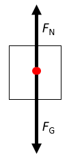
Draw a force diagram for a cup of coffee on a table.

Solution
- Analyse the situation: The object of interest is the cup. We regard the cup, with its contents, as the system (object) of interest. The object is at rest on a flat surface.
- Identify the forces acting on the object: We know that gravity acts on the object. Because the object rests on a surface there must also be a normal force. The situation does not suggest any other forces at work.
- Determine the direction of each force: We know that gravity acts downwards. The normal force is exerted by the surface on the object and therefore acts upwards, perpendicular to the surface.
- Determine the relative size of each force: The object is at rest. That means the resultant force is zero, and so the two forces must be balanced.
We can now proceed to draw the diagram. We use a box or large dot to represent the object, rather than drawing the actual cup of coffee. We then add arrows to represent the individual forces, with the arrowheads pointing in the direction of the force and the length of an arrow representing the relative size of the force.
Example 2.2
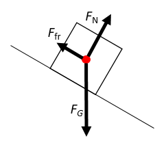
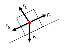
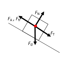
Draw a force diagram for a car sliding down a slope.

Solution
- Analyse the situation: The car is the system. It is moving and the movement is at an angle.
- Identify the forces acting on the object: We know that gravity acts on the system. Because the system is in contact with a solid surface, we know there is also a normal force acting on the system. We also know that the system is moving over the surface, which tells us a frictional force will be acting on the system. The movement is not due to an applied force.
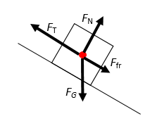
- Determine the direction of each force: Gravity acts directly downwards. The normal force is exerted by the surface and is therefore upwards. However, remember that the normal force is always perpendicular to the surface, and therefore it is not in a directly opposite direction to the gravitational force. The car moves down the slope, and because friction is a force that opposes the motion, we therefore know that friction must act in the direction opposite to the motion.
- Determine the relative size of each force: The car moves parallel to the surface and down the slope. That means forces in the vertical direction are not balanced; the gravitational force must be bigger than the opposing normal force. The force of friction is the only force acting parallel to the surface; there is no applied force.
We can now draw the completed force diagram:
Example 2.3
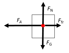
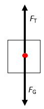
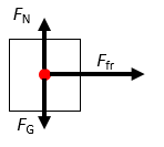
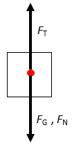
A woman is pushing her mother in a wheelchair. Which diagram correctly represents the forces acting on the person in the wheelchair?

| Diagram A | Diagram B |
 |
 |
Solution
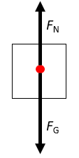
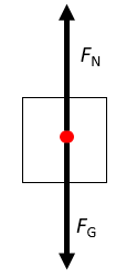
The object of interest is the person sitting in the wheelchair, not the combination of the wheelchair and the person. The person is stationary; it is only the wheelchair that is moving. This means that there are no horizontal forces acting on the person. Diagram A is therefore incorrect. Diagram B shows that only two vertical forces act on the object and that they are balanced, which correctly describes the situation of a stationary person in a moving wheelchair.
Example 2.4
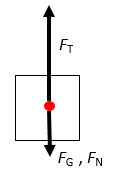
Three potted plants sit on a hanging shelf, which is not moving. Which is the correct force diagram for the shelf?

| Diagram A | Diagram B |
 |
 |
Solution
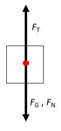
The object of interest is the shelf. Because the shelf is hanging but not moving, we know that the resultant force in both the vertical and the horizontal direction must be zero. There are no horizontal forces at work, only vertical forces. Gravity acts downwards on the shelf. However, the three pots also exert a downward force on the shelf. All the downward forces are balanced by two upward-acting tension forces, one in each cable. If we were to draw these forces separately, it would look like this:
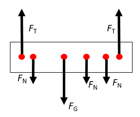
However, it is preferable to draw the forces all relative to one point, so the combined diagram would look as shown in Diagram A, showing that all the downward forces are balanced by the upward forces.
Diagram B is not correct, because the normal forces are acting downward – they represent the pots pushing down on the shelf. The diagram as shown in B would have been correct if we were asked to draw a force diagram for the pots.
The best way to become confident at drawing force diagrams is to practise. Try this exercise on your own.
Exercise 2.1
- Draw force diagrams for the following situations:
- A crate being pulled up a ramp using a rope
- A light bulb hanging from the ceiling
- A car skidding across the road after the brakes have locked.
- Match each of the following situations with the correct force diagram.
- A ball being dropped from the top of a 10-storey building
- A baby pram being pushed at a constant speed
- A ball as it is being kicked from a stationary position to a goal post
Diagram A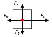 |
Diagram B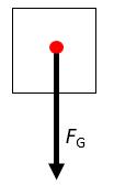 |
Diagram C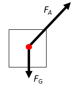 |
Diagram D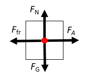 |
The full solutions are at the end of the unit.
Summary
In this unit you have learnt the following:
- A force diagram shows the forces acting on an object or a system of interest.
- Forces are represented by arrows that point in the direction of the force. The length of an arrow represents the relative size of the force.
- Force diagrams are conventionally labelled to show the type of force. The size of the force can also be included.
Unit 2: Assessment
Suggested time to complete: 15 minutes
- A car is towing another car, which has broken down, using a tow rope. They have to travel through a hilly landscape to get to the garage. Draw a force diagram for the car being towed at each of the following stages of their journey.
- Early on in their journey they travel up a hill.
- The car in front loses speed the further it goes up the hill.
- After they reach the top of the hill, they have to travel down a gentle slope again. The driver of the second car has to apply the brakes to keep the rope taut.
- Draw a force diagram to represent a lift in a tall building:
- when it is stationary at the fifth floor of the building, just after three people stepped inside
- when it is moving towards the first floor, slowing down as it approaches its stop.
- Katlego is practising her tennis backhand shots at the practice wall near the tennis court. Which force diagram represents:
- the ball just after Katlego hits it with the racket?
- the ball when it hits the wall?
Diagram A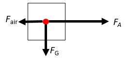 |
Diagram B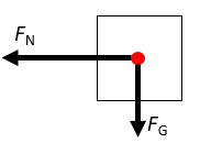 |
Diagram C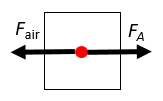 |
Diagram D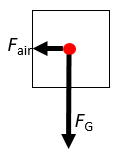 |
The full solutions are at the end of the unit.
Unit 2: Solutions
Exercise 2.1
- .
- .
- .
- .
- .
- .
- .
- .
- .
- .
Unit 2: Assessment
- .
- .
- .

- .
- .
- .
- .
- .
- .
- ..
- .
- .
- .
Media Attributions
- Img01_F1 car © Pablo Franco is licensed under a CC0 (Creative Commons Zero) license
- Img02_Force diagram 1 © DHET is licensed under a CC BY (Attribution) license
- Img03_Cup © David Schwarzenberg is licensed under a CC0 (Creative Commons Zero) license
- Img04_Force diagram 2 © DHET is licensed under a CC BY (Attribution) license
- Img05_Car © Tommasso Pacchioli is licensed under a CC0 (Creative Commons Zero) license
- Img06_Force diagram 3 © DHET is licensed under a CC BY (Attribution) license
- Img09_Wheelchair © Stefano Intintoli is licensed under a CC0 (Creative Commons Zero) license
- Img07_Force diagram 4 © DHET is licensed under a CC BY (Attribution) license
- Img08_Force diagram 5 © DHET is licensed under a CC BY (Attribution) license
- Img010_Shelf © Oogway is licensed under a CC0 (Creative Commons Zero) license
- Img011_Force diagram 6 © DHET is licensed under a CC BY (Attribution) license
- Img012_Force diagram 7 © DHET is licensed under a CC BY (Attribution) license
- Img029_Force diagram 24 © DHET is licensed under a CC BY (Attribution) license
- Img013_Force diagram 8 © DHET is licensed under a CC BY (Attribution) license
- Img014_Force diagram 9 © DHET is licensed under a CC BY (Attribution) license
- Img015_Force diagram 10 © DHET is licensed under a CC BY (Attribution) license
- Img016_Force diagram 11 © DHET is licensed under a CC BY (Attribution) license
- Img017_Force diagram 12 © DHET is licensed under a CC BY (Attribution) license
- Img018_Force diagram 13 © DHET is licensed under a CC BY (Attribution) license
- Img019_Force diagram 14 © DHET is licensed under a CC BY (Attribution) license
- Img020_Force diagram 15 © DHET is licensed under a CC BY (Attribution) license
- Img021_Force diagram 16 © DHET is licensed under a CC BY (Attribution) license
- Img022_Force diagram 17 © DHET is licensed under a CC BY (Attribution) license
- Img023_Force diagram 18 © DHET is licensed under a CC BY (Attribution) license
- Img024_Force diagram 19 © DHET is licensed under a CC BY (Attribution) license
- Img025_Force diagram 20 © DHET is licensed under a CC BY (Attribution) license
- Img026_Force diagram 21 © DHET is licensed under a CC BY (Attribution) license
- Img027_Force diagram 22 © DHET is licensed under a CC BY (Attribution) license
- Img028_Force diagram 23 © DHET is licensed under a CC BY (Attribution) license
a diagram to show the collective external forces acting on an object
system on which external forces act
